HelpDesk
How to Create an Interactive Voice Response (IVR) Diagram
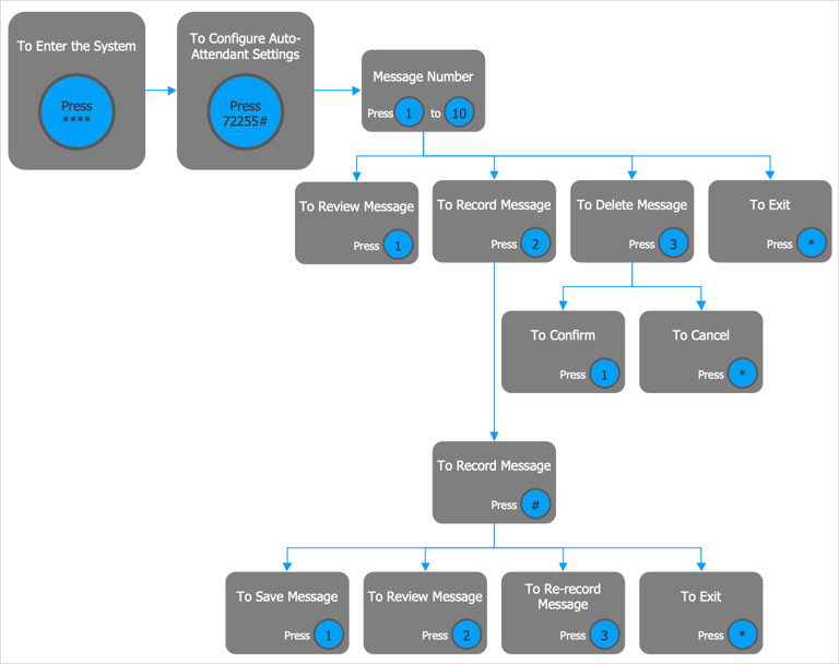
Interactive Voice Response (IVR) Diagram is used to create and conduct the Interactive Voice Response systems for call-centers and voice mail services. IVR diagrams intended to visualize the logical and physical structure of Interactive voice response systems. ConceptDraw solution for Interactive Voice Response (IVR) Diagram allows you to create and communicate the Interactive Voice Response diagram of any complexity. Interactive Voice Response (IVR) System is a telecommunication technology that enables a computer to automatically process voice and touch phone signals. IVR systems allows users to interact through a computer with various service systems, available by telephone. The objective of IVR system is to reduce customer service costs by delivering self service to customers and guiding them to the information that they look for.HelpDesk
How to Create Flowchart Using Standard Flowchart Symbols
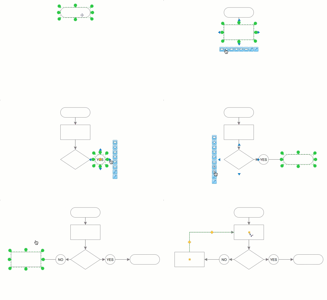
Flowcharts are used to display an algorithm for consistent execution of certain steps. Flowchart is probably the easiest way to make a graphical representation of any process. Flowcharts use the set of standard geometric symbols and arrows to define relationships. ConceptDraw DIAGRAM allows you to create professional flowchart quickly and easily. The ability to create flowcharts is contained in the Flowcharts solution. The solution provides a set of special tools for creating flowcharts.Network Layout
The Network Layout Diagram visually illustrates the arrangement of computers, nodes and other network appliances, such as servers, printers, routers, switches, hubs, and their relationships between each other. The network layout and placement of servers greatly influence on the network security and network performance. Elaboration of robust Network Layout Diagram is especially important when visualizing already existing network in order to understand its complexity; when troubleshooting the network issues; designing, documenting and implementing new network configurations; extending, modifying, or moving an existing network to other location. Through the careful thinking the network plan and designing the clear Network Layout Diagram, you can be confident in result on the stage of network implementation and to solve faster the problems appearing in network infrastructure. ConceptDraw DIAGRAM enhanced with Computer Network Diagrams solution from Computer and Networks area perfectly suits for drawing Network Layout Diagrams for different network topologies.
- Venn Diagram Concept Map
- Circuits and Logic Diagram Software | Electrical Symbols , Electrical ...
- Concept maps - Vector stencils library | Concept Maps | Concept ...
- Basic Flowchart Symbols and Meaning | Process Flowchart | Circuits ...
- Concept Mapping | Basic Diagramming | Concept Maps | Concept ...
- Design elements - Logic gate diagram | Electrical Symbols ...
- Cisco LAN - Vector stencils library | How to Make a Web Page from ...
- Modelling Concepts for Business Engineering - EPC | Concept ...
- Design elements - Logic gate diagram | Electrical Drawing Software ...
- Concept Maps
- Block Diagram | Basic Flowchart Symbols and Meaning | Design ...
- Electrical Drawing Software and Electrical Symbols | Circuits and ...
- Mathematics | Mathematics Symbols | Mathematical Diagrams | Mind ...
- Concept Map | How to Create a Concept Map in ConceptDraw PRO ...
- Electrical Symbols , Electrical Diagram Symbols | Cross-Functional ...
- ConceptDraw PRO Network Diagram Tool | DES Network. Computer ...
- Logic Vendiagram Problem Set
- Circuits and Logic Diagram Software | Electrical Symbols , Electrical ...
- How To Make a Concept Map | How to Add a Concept Map to a ...
- What Identify Parking In Crow Foot Notation


