HelpDesk
How to Create an ERD Diagram
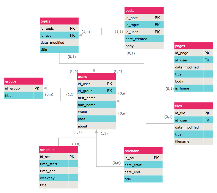
ERD (entity relationship diagram) is used to show the logical structure of databases. It represents the interrelationships between components of database (entities). Entity relationship diagrams are a widely used in software engineering. Using ERD software engineers can control the every aspect of database development. ER diagram can be used as guide for testing and communicating before the release of software product. ERD displays data as entities that are connected with connections that show the relationships between entities. There is some ERD notations used by data bases developers for representing the relationships between the data objects. ConceptDraw PRO and its ERD solution allow you to build ERD diagram of any notation.- ERD (crow's foot notation )
- Design elements - ER diagram (Chen notation ) | Entity Relationship ...
- ConceptDraw PRO Database Modeling Software | Database ...
- Entity Relationship Diagram Data Model
- Logical Diagram Database
- Data Modeling Diagram | Data modeling with ConceptDraw PRO ...
- ConceptDraw PRO Database Modeling Software | Data Modeling ...
- Logical Data Model Notation
- ERD Symbols and Meanings | Data Flow Diagram Software ...
- Data Modeling with Entity Relationship Diagram | IDEF0 Flowchart ...
- Data Modeling Notations Ssadm
- ER Diagram Tools For Mac Logical Model
- Components of ER Diagram | ERD Symbols and Meanings | Entity ...
- Data flow Model Diagram
- Data Flow Diagram Model | Data Flow Diagram Symbols . DFD ...
- ERD Symbols and Meanings | Entity Relationship Diagram Symbols ...
- Physical And Logical Dfd
- Entity Relationship Diagram Symbols | Basic Flowchart Symbols and ...
- Data Flow Diagram Model | Structured Systems Analysis and Design ...
