HelpDesk
How to Create a Fault Tree Analysis Diagram (FTD) in ConceptDraw PRO
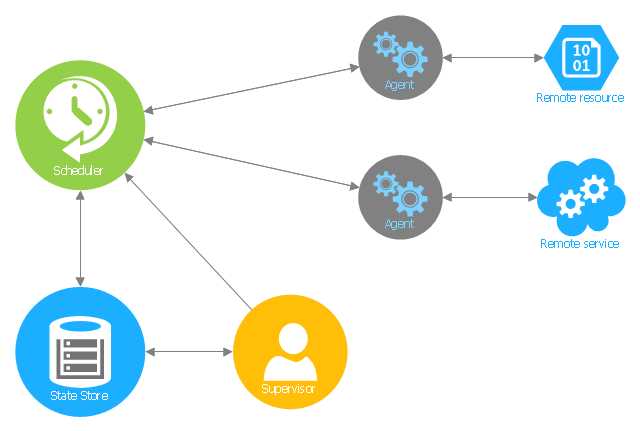
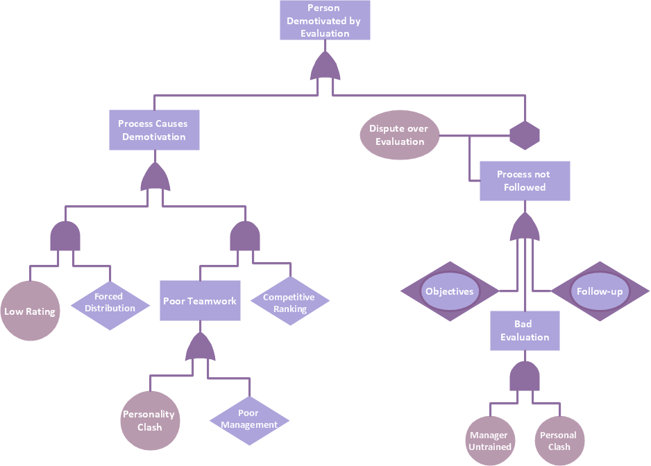
Fault Tree Diagram are logic diagram that shows the state of an entire system in a relationship of the conditions of its elements. Fault Tree Diagram are used to analyze the probability of functional system failures and safety accidents. ConceptDraw PRO allows you to create professional Fault Tree Diagrams using the basic FTD symbols. An FTD visualize a model of the processes within a system that can lead to the unlikely event. A fault tree diagrams are created using standard logic symbols . The basic elements in a fault tree diagram are gates and events.This Azure cloud architecture pattern diagram template was created on the base of figure in the article "Scheduler Agent Supervisor Pattern" from the Microsoft Developer Network (MSDN) website.
"Scheduler Agent Supervisor Pattern.
Coordinate a set of actions across a distributed set of services and other remote resources, attempt to transparently handle faults if any of these actions fail, or undo the effects of the work performed if the system cannot recover from a fault. This pattern can add resiliency to a distributed system by enabling it to recover and retry actions that fail due to transient exceptions, long-lasting faults, and process failures. ...
An application performs tasks that comprise a number of steps, some of which may invoke remote services or access remote resources. The individual steps may be independent of each other, but they are orchestrated by the application logic that implements the task.
Whenever possible, the application should ensure that the task runs to completion and resolve any failures that might occur when accessing remote services or resources. ...
If the application detects a more permanent fault from which it cannot easily recover, it must be able to restore the system to a consistent state and ensure integrity of the entire end-to-end operation. ...
The Scheduler Agent Supervisor pattern defines the following actors. These actors orchestrate the steps (individual items of work) to be performed as part of the task (the overall process):
- The Scheduler arranges for the individual steps that comprise the overall task to be executed and orchestrates their operation. ...
- The Agent contains logic that encapsulates a call to a remote service, or access to a remote resource referenced by a step in a task. ...
- The Supervisor monitors the status of the steps in the task being performed by the Scheduler. ...
The Scheduler, Agent, and Supervisor are logical components and their physical implementation depends on the technology being used." [msdn.microsoft.com/ ru-RU/ library/ dn589780.aspx]
The Azure cloud system architecture diagram template "Scheduler agent supervisor pattern" for the ConceptDraw PRO diagramming and vector drawing software is included in the Azure Architecture solutin from the Computer and Networks area of ConceptDraw Solution Park.
Graphics Software for Business
If you want to use effective methods for your business, you may need a tool which may let you represent your ideas and goals in graphic way. Software with different flowchart templates for each type of business will be your lifesaver. ConceptDraw PRO with its business samples, libraries and design elements is a point to start.Graphic Technologies
Graphics Technology looks at how to communicate graphically, develop ability to create graphical presentations for varied needs, understand standards and special conventions, develop specific techniques and build an understanding of the impact of graphical presentation on society. If you want to use effective methods for your work, you may need a tool which may let you represent your ideas and goals in graphic way.
 Cisco Network Diagrams
Cisco Network Diagrams solution extends ConceptDraw PRO software with samples, templates and libraries of vector stencils for drawing the Cisco computer network diagrams.
The vector stencils library "Cisco network topology" contains 89 symbols of Cisco network devices and design elements for drawing computer network topology diagrams.
"There are two basic categories of network topologies:
(1) Physical topologies,
(2) Logical topologies.
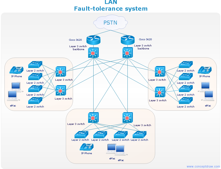
The shape of the cabling layout used to link devices is called the physical topology of the network. This refers to the layout of cabling, the locations of nodes, and the interconnections between the nodes and the cabling. The physical topology of a network is determined by the capabilities of the network access devices and media, the level of control or fault tolerance desired, and the cost associated with cabling or telecommunications circuits.
The logical topology in contrast, is the way that the signals act on the network media, or the way that the data passes through the network from one device to the next without regard to the physical interconnection of the devices." [Network topology. Wikipedia]
The symbols example "Cisco network topology - Vector stencils library" was created using the ConceptDraw PRO diagramming and vector drawing software extended with the Cisco Network Diagrams solution from the Computer and Networks area of ConceptDraw Solution Park.
www.conceptdraw.com/ solution-park/ computer-networks-cisco
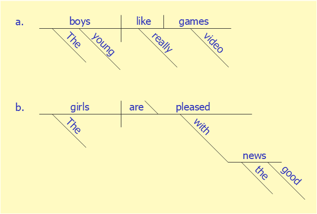
This sentence diagram example was redesigned from the Wikipedia file: Examples of Reed-Kellogg diagrams.jpg.
[en.wikipedia.org/ wiki/ File:Examples_ of_ Reed-Kellogg_ diagrams.jpg]
This file is licensed under the Creative Commons Attribution-Share Alike 3.0 Unported license. [creativecommons.org/ licenses/ by-sa/ 3.0/ deed.en]
"Most methods of diagramming in pedagogy are based on the work of Alonzo Reed and Brainerd Kellogg in their book Higher Lessons in English, first published in 1877, though the method has been updated with recent understanding of grammar. Reed and Kellogg were preceded, and their work probably informed, by W. S. Clark, who published his "balloon" method of depicting grammar in his 1847 book A Practical Grammar: In Which Words, Phrases & Sentences are Classified According to Their Offices and Their Various Relationships to Each Another.
Some schoolteachers continue to use the Reed-Kellogg system in teaching grammar, but others have discouraged it in favor of more modern tree diagrams. However, these modern tree structures draw on techniques that were already present in Reed-Kellogg diagrams. Reed and Kellogg defend their system in the preface to their grammar:
The Objections to the Diagram. - The fact that the pictorial diagram groups the parts of a sentence according to their offices and relations, and not in the order of speech, has been spoken of as a fault. It is, on the contrary, a merit, for it teaches the pupil to look through the literary order and discover the logical order. He thus learns what the literary order really is, and sees that this may be varied indefinitely, so long as the logical relations are kept clear.
The assertion that correct diagrams can be made mechanically is not borne out by the facts. It is easier to avoid precision in oral analysis than in written. The diagram drives the pupil to a most searching examination of the sentence, brings him face to face with every difficulty, and compels a decision on every point.
These statements bear witness to the fact that Reed-Kellogg diagrams abstract away from actual word order in order to focus more intently on how words in sentences function and relate to each other." [Sentence diagram. Wikipedia]
The examples of Reed-Kellogg diagrams was created using the ConceptDraw PRO diagramming and vector drawing software extended with the Language Learning solution from the Science and Education area of ConceptDraw Solution Park.
Network Diagrams for Bandwidth Management
A perfect tool to draw network diagram for bandwidth management. Computer & Networks solution provides the symbol libraries with pre-designed network graphic elements. Use Computer & Networks solution to draw the network diagrams for bandwidth management for Cisco networks, Apple networks, IVR networks, GPRS networks, wi-fi networks, LAN and WAN.
"Most methods of diagramming in pedagogy are based on the work of Alonzo Reed and Brainerd Kellogg in their book Higher Lessons in English, first published in 1877, though the method has been updated with recent understanding of grammar. ...
Some schoolteachers continue to use the Reed-Kellogg system in teaching grammar, but others have discouraged it in favor of more modern tree diagrams. However, these modern tree structures draw on techniques that were already present in Reed-Kellogg diagrams. Reed and Kellogg defend their system in the preface to their grammar:
The Objections to the Diagram.--The fact that the pictorial diagram groups the parts of a sentence according to their offices and relations, and not in the order of speech, has been spoken of as a fault. It is, on the contrary, a merit, for it teaches the pupil to look through the literary order and discover the logical order. He thus learns what the literary order really is, and sees that this may be varied indefinitely, so long as the logical relations are kept clear.
The assertion that correct diagrams can be made mechanically is not borne out by the facts. It is easier to avoid precision in oral analysis than in written. The diagram drives the pupil to a most searching examination of the sentence, brings him face to face with every difficulty, and compels a decision on every point.
... Reed-Kellogg diagrams abstract away from actual word order in order to focus more intently on how words in sentences function and relate to each other.
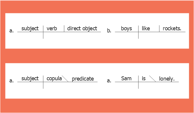
The Reed-Kellogg System. Simple sentences in the Reed-Kellogg system are diagrammed in accordance with the ... basic schemata" shown in this diagram example. [Sentence diagram. Wikipedia]
The example "The Reed-Kellogg system - Basic schemata" was created using the ConceptDraw PRO diagramming and vector drawing software extended with the Language Learning solution from the Science and Education area of ConceptDraw Solution Park.
- What Is A Fault Tree Analysis
- Fault Tree Analysis Diagrams | Word Exchange | Process Flowchart ...
- Root cause analysis tree diagram - Template | Fault Tree Diagram ...
- Design elements - Trees and plants | Design elements - Fault tree ...
- Fault Tree Analysis Diagrams Solution
- Logical symbols - Vector stencils library | Fault Tree Analysis ...
- Fault Tree Analysis Diagrams | Person demotivated by evaluation ...
- Design elements - Fault tree analysis diagrams | Audit failure - Fault ...
- Venn Diagram | Venn Diagrams | Fault Tree Diagram | Sample Venn ...
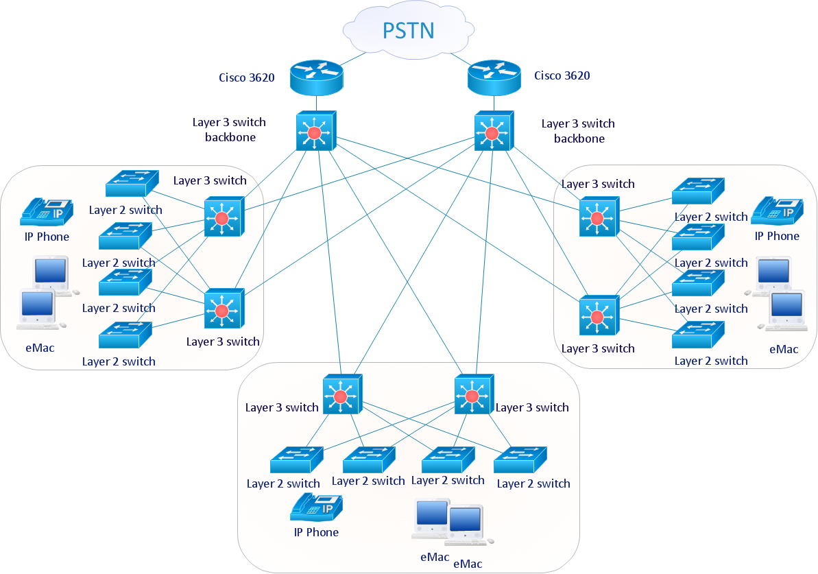
- Cisco LAN fault -tolerance system - diagram | How to Draw a ...
- Electrical Drawing Software | Engineering | How to Create a Fault ...
- Venn Diagrams | Fault Tree Diagram | ConceptDraw Solution Park ...
- Design elements - Logic gate diagram | Electrical Drawing Software ...
- How to Create a Fault Tree Analysis Diagram (FTD) in ConceptDraw ...
- Cross-Functional Flowchart (Swim Lanes) | | How to Create a Fault ...
- Design elements - Logic gate diagram
- Fault Tree Analysis Diagrams | Active Directory Diagram ...
- Logic gate diagram - Template | Engineering | Circuits and Logic ...
- Logic gate diagram - Template | Design elements - Logic gate ...
- Design elements - Logic gate diagram



-cisco-network-topology---vector-stencils-library.png--diagram-flowchart-example.png)
-cisco-network-topology---vector-stencils-library.png--diagram-flowchart-example.png)


-cisco-network-topology---vector-stencils-library.png--diagram-flowchart-example.png)


-cisco-network-topology---vector-stencils-library.png--diagram-flowchart-example.png)


-cisco-network-topology---vector-stencils-library.png--diagram-flowchart-example.png)


