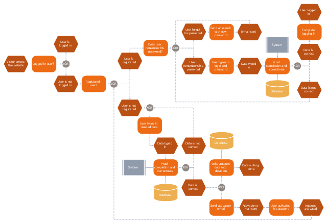
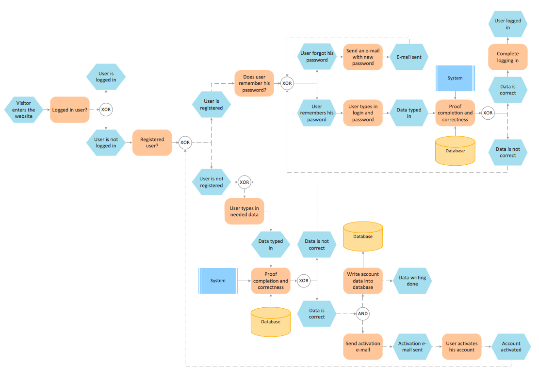
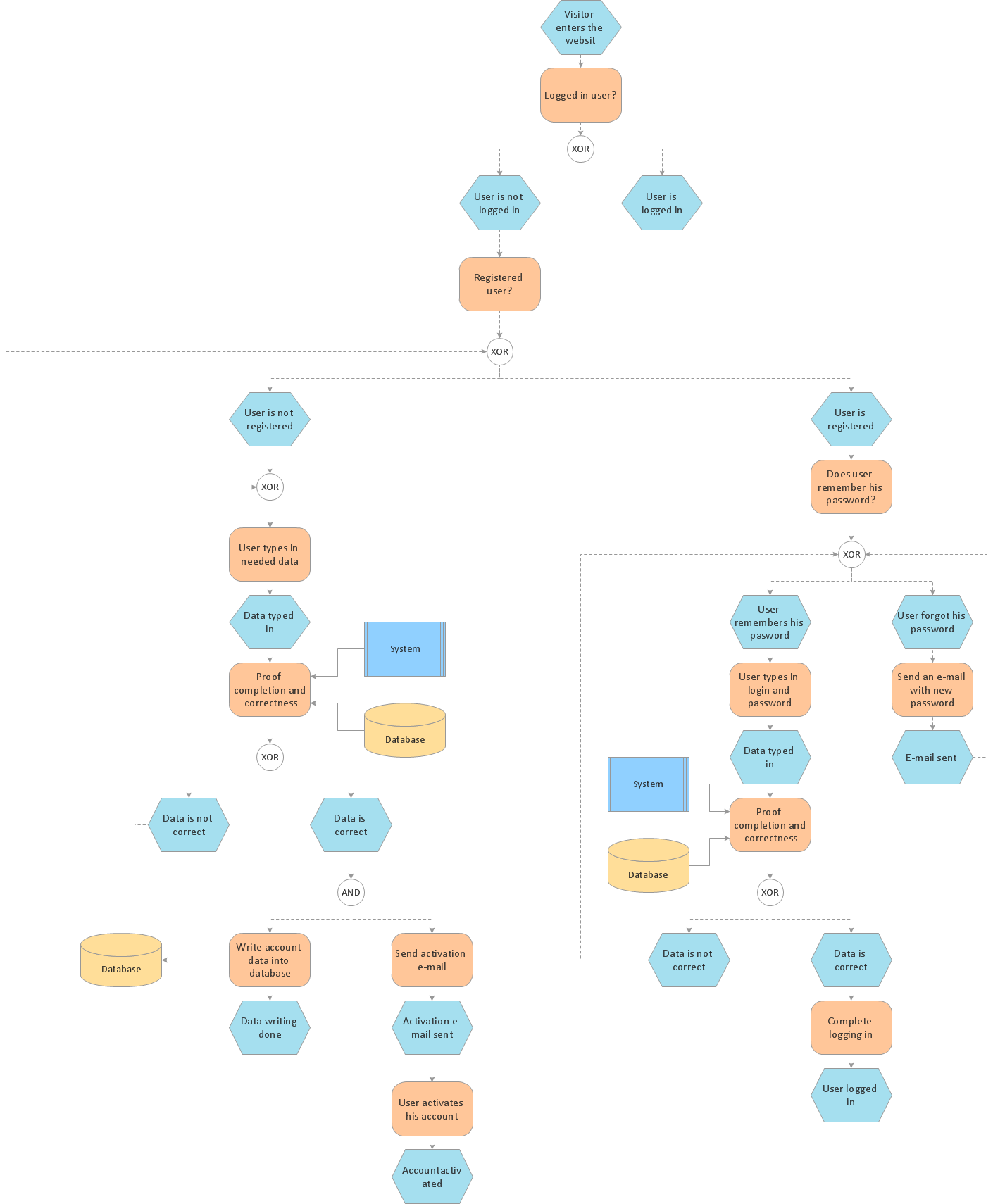
This event-driven process chain (EPC) flowchart sample depicts the login and registration processing.
"In computer security, a login or logon refers to the credentials required to obtain access to a computer system or other restricted area. Logging in or on and signing in or on is the process by which individual access to a computer system is controlled by identifying and authenticating the user through the credentials presented by the user.
Once a user has logged in, they can then log out or log off when access is no longer needed. To log out is to close off one's access to a computer system after having previously logged in." [Login. Wikipedia]
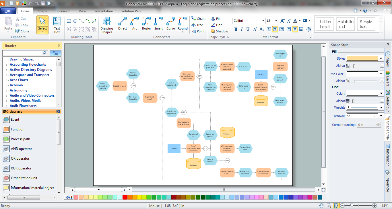
The event-driven process chain flowchart example "Login and registration processing" was created using the ConceptDraw PRO diagramming and vector drawing software extended with the Basic EPC solution from the Business Processes area of ConceptDraw Solution Park.
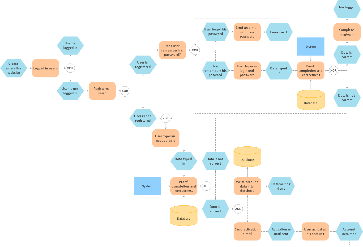
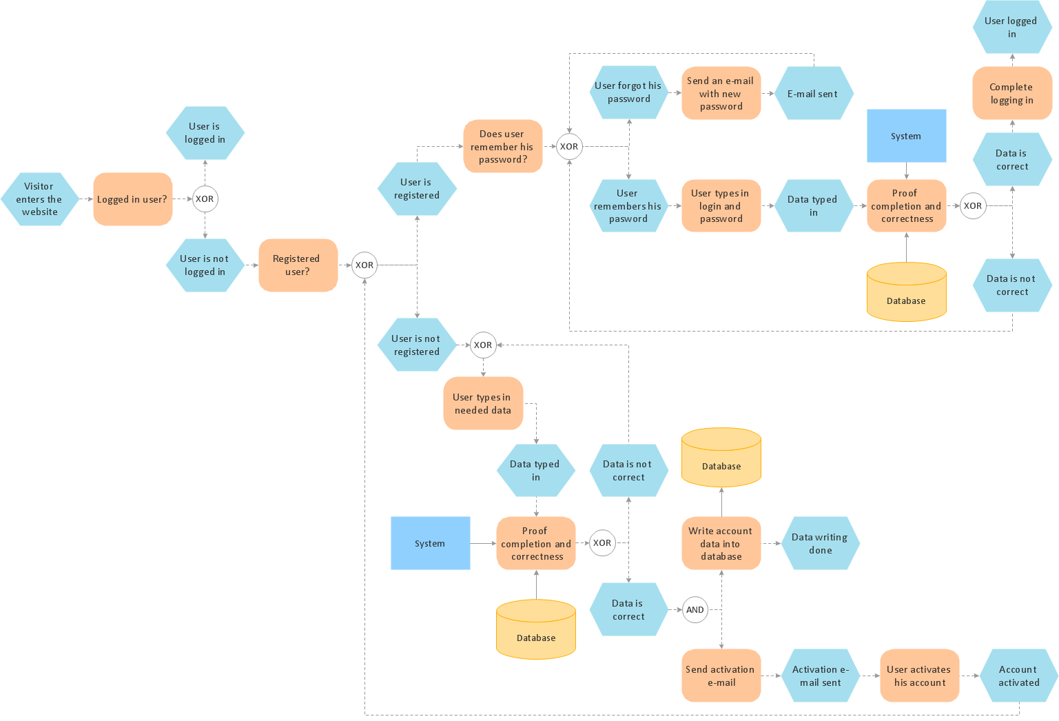
This computer security EPC diagram sample depicts the login and registration processing flow.
"In computer security, a login or logon refers to the credentials required to obtain access to a computer system or other restricted area. Logging in or on and signing in or on is the process by which individual access to a computer system is controlled by identifying and authenticating the user through the credentials presented by the user.
Once a user has logged in, they can then log out or log off when access is no longer needed. To log out is to close off one's access to a computer system after having previously logged in." [Login. Wikipedia]
The event-driven process chain (EPC) flowchart example "Login and registration processing" was created using the ConceptDraw PRO diagramming and vector drawing software extended with the Event-driven Process Chain Diagrams solution from the Business Processes area of ConceptDraw Solution Park.
Flowchart
The Flowcharts are widespread in various fields and include the multitude of types. They are dedicated to representation the algorithms, processes, workflows of any complexity in a clear and intuitive format. The Flowcharts are commonly used in software development as a visual tool for illustration algorithms and logic of computer programs, in business for illustration business scenarios, in education, and so on. For drawing the Flowchart are used the special object blocks, among them rectangle or box used to represent an activity or step, rounded box or oval to depict Start / End, diamond to represent the decision point (involves the branching yes/no), circle used to represent the point of connection, parallelogram to represent the Input / Output, and some others. With ConceptDraw DIAGRAM including Flowcharts solution it is easy to create professional-looking Flowchart diagrams of any complexity and any degree of detailing. Succeed in drawing the Flowcharts using quick-start templates, predesigned samples and extensive libraries of ready-made flowchart symbols, blocks and icons.EPC (Event-driven Process Chain) Flowcharts
The Event - driven Process Chain ( EPC ) allows managers visually present business process models for making decisions for business processes improvement. Event-Driven Process Сhain Diagrams for improvement throughout an organisation.Process Modelling using Event-driven Process chain
Event-Driven Process Chain Diagrams for improvement throughout an organisation. ConceptDraw DIAGRAM - business process mapping software that reduces the time needed to create a business process model and its excellent business process improvement tools.Formalization and Verification of Event-driven Process chain
EPC or The Event - driven Process Chain diagrams that provide Enterprise Resource Planning improvement. ConceptDraw DIAGRAM - software that reduces the time needed to create a business process model.How to Help Customers be More Productive
Presenting you with a drawing program which could really surprise you with their great functionality. Don't know how to start to draw Connector's improvement? Curious how should diagramming software work? Drawing programs involve a lot of things like designs in an illustrative way, creating an cherts, Tools to create high end graphics, create dashboards, using your data and many other technical aspects do it in a much professional and in a quick way.EPC
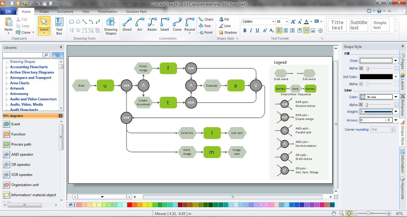
How do you make usually the EPC diagrams? It is quite complex and lengthy process. But now thanks to the ConceptDraw DIAGRAM diagramming and vector drawing software extended with Event-driven Process Chain Diagrams EPC solution from the Business Processes area of ConceptDraw Solution Park this process became simple and fast.The vector stencils library "Cybersecurity" contains 24 cybersecurity icons.
Use it to design your computer and telecom illustrations and infographics with ConceptDraw PRO diagramming and vector drawing software.
The vector stencils library "Cybersecurity" is included in the Computers and Communications solution from the Illustration area of ConceptDraw Solution Park.
Use it to design your computer and telecom illustrations and infographics with ConceptDraw PRO diagramming and vector drawing software.
The vector stencils library "Cybersecurity" is included in the Computers and Communications solution from the Illustration area of ConceptDraw Solution Park.
Business process Flow Chart — Event-Driven Process chain (EPC) diagrams
Event-Driven Process chain Diagrams for improvement throughout an organisation. Best software for Process Flow Diagram. The Event-driven Process Chain (EPC) Diagrams allows managers to plan processes and resources.The Best Tool for Business Process Modeling
The EPC diagram shows various business processes in terms of work flows. Event-Driven Process chain Diagrams for improvement throughout an organisation. ConceptDraw DIAGRAM - business process mapping software that reduces the time needed to create a business process model and is excellent business process improvement tools.Databases Access Objects Model with ConceptDraw DIAGRAM
ConceptDraw Basic gives the opportunity of interaction with any ODBC-compatible databases. For this the Database Access Objects Model is provided. All calls to the database are made by certain methods of objects of this model.HelpDesk
How to Activate ConceptDraw After Purchasing from the Web Store
Here you will find an explanation of how activation works when ConceptDraw products are purchased from the ConceptDraw web site. You do not have to manually activate your software. Your license key is saved in your account. Your license is automatically added to your ConceptDraw.com account and saved there permanently. Thus you don’t have to worry about losing your license if your computer crashes or you want to install on a second system.EPC Engineering
ConceptDraw DIAGRAM is a powerful diagramming and vector drawing software. Extended with Event-driven Process Chain Diagrams EPC solution from the Business Processes Area, ConceptDraw DIAGRAM became the ideal EPC Engineering software.- State Chart Diagram Of Login Process Of Online Banking System
- Login Flow Chart Sample
- Dfd Login Process
- Login Process Data Flow Diagram Example
- Er Diagram For User Login
- Flowchart Diagram For Students Login And Registration
- Flowchart For Login System
- Erd For Login Website
- Flowchart | Login and registration processing - EPC diagram ...
- UML Use Case Diagram Example Social Networking Sites Project ...
- Database Flowchart Login
- Functional Block Diagram User Login
- Login History Er Diagram
- Process Flowchart | Basic Flowchart Symbols and Meaning | Login ...
- Dfd Diagram For Login System
- Login State Chart
- Dfd Of Login Page
- Flowchart For A Login System Using Username And Password
- Create A Login Flowcharting With Database

