The vector stencils library "Network layout floorplan" contain 34 symbol icons for drawing computer network floor plans and communication equipment and cabling layouts.
"Networking hardware may also be known as network equipment or computer networking devices. Units which are the last receiver or generate data are called hosts or data terminal equipment.
All these terms refer to devices facilitating the use of a computer network. Specifically, they mediate data in a computer network. ...
Typically, networking hardware includes gateways, routers, network bridges, switches, hubs, and repeaters. But it also includes hybrid network devices such as multilayer switches, protocol converters, bridge routers, proxy servers, firewalls, network address translators, multiplexers, network interface controllers, wireless network interface controllers, modems, ISDN terminal adapters, line drivers, wireless access points, networking cables and other related hardware.
The most common kind of networking hardware today is a copper-based Ethernet adapter because of its standard inclusion on most modern computer systems. Wireless networking has, however, become increasingly popular, especially for portable and handheld devices.
Other hardware prevalent in computer networking includes data center equipment (such as file servers, database servers and storage areas), network services (such as DNS, DHCP, email, etc.) as well as devices which assure content delivery." [Networking hardware. Wikipedia]
The shapes example "Design elements - Network layout floorplan" was created using the ConceptDraw PRO diagramming and vector drawing software extended with the Network Layout Floor Plans solution from the Computer and Networks area of ConceptDraw Solution Park.
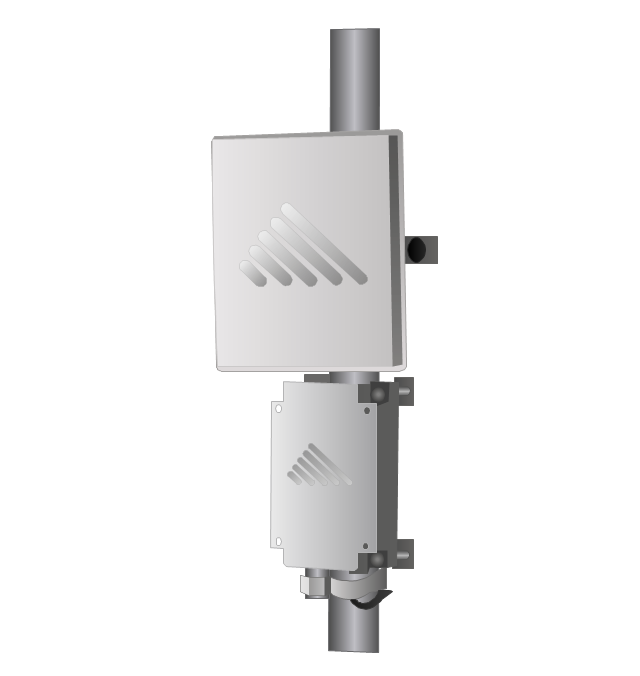
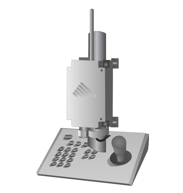
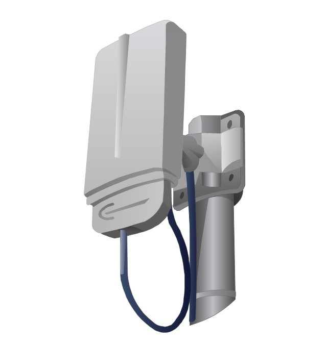
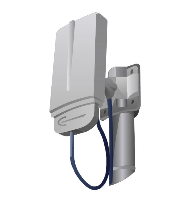
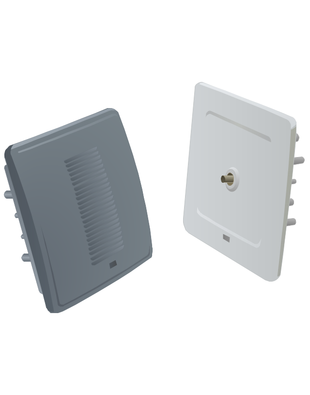
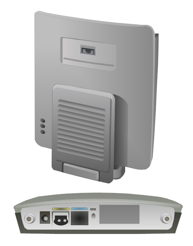
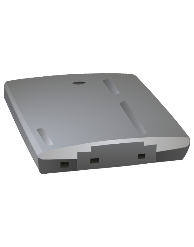
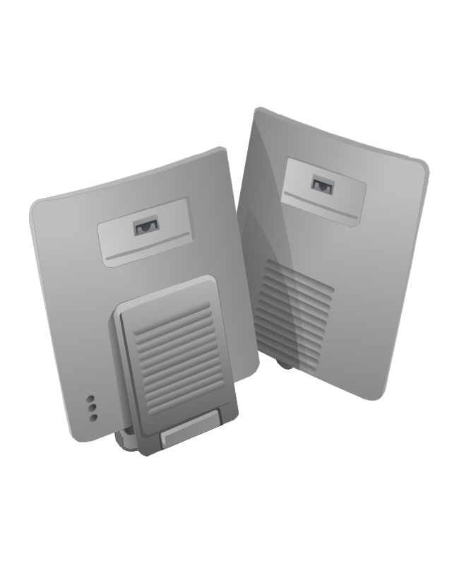
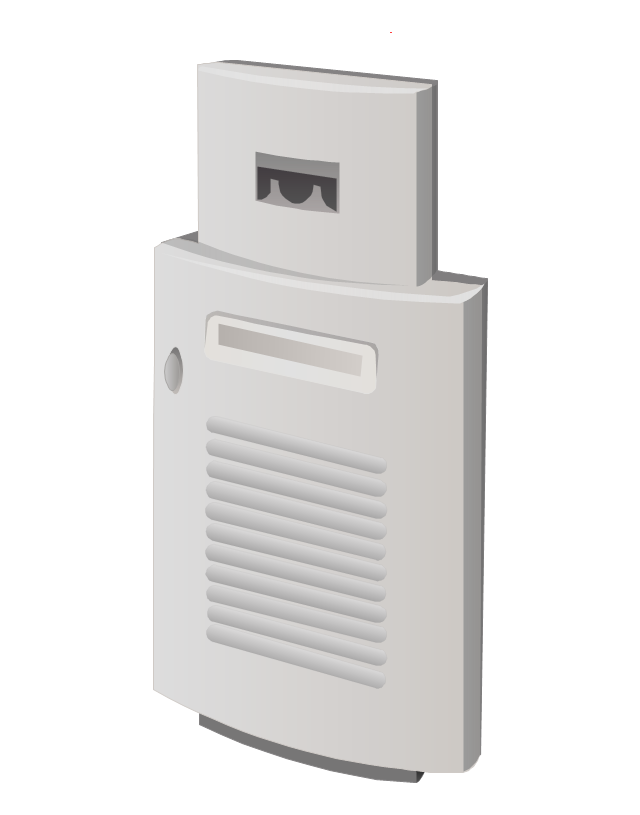
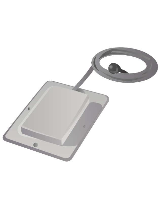
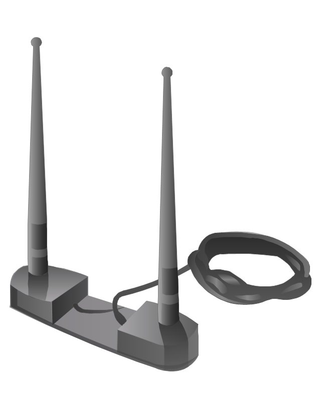
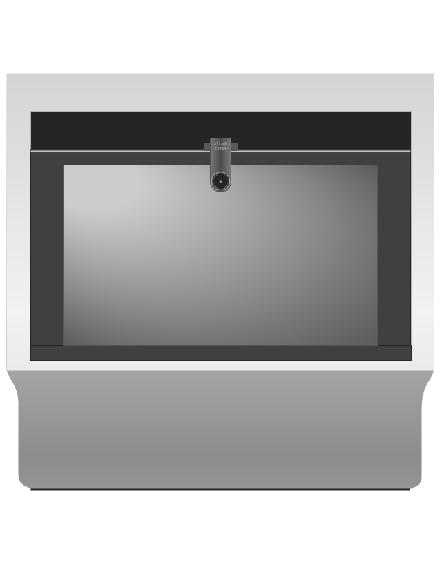
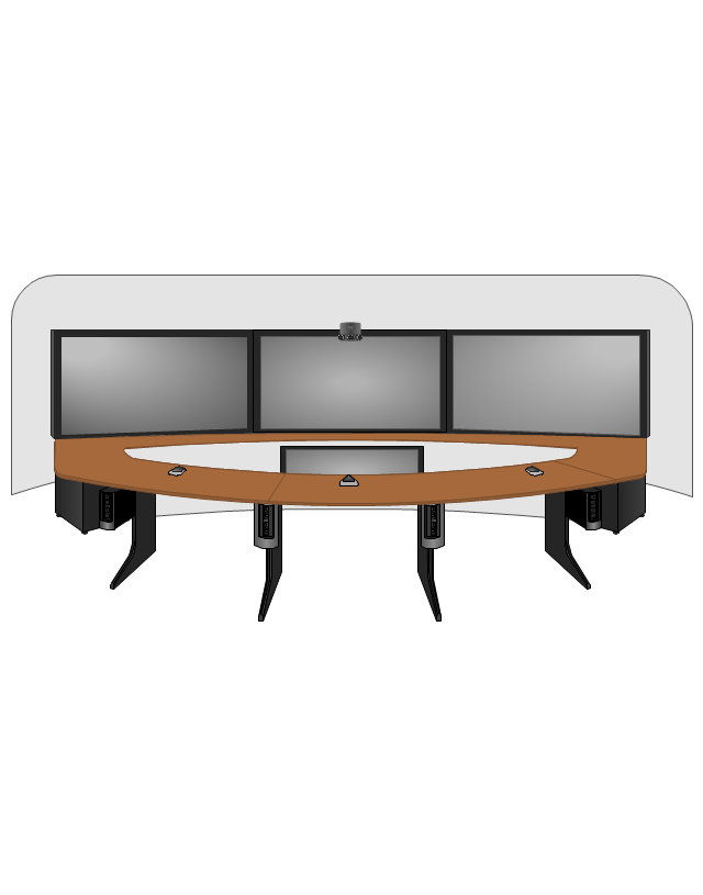
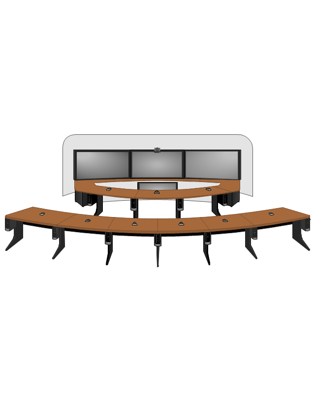
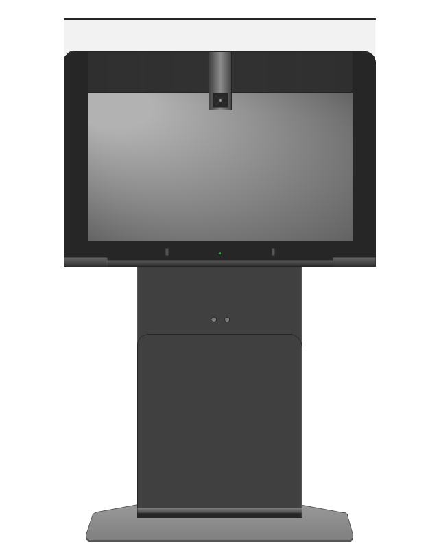
The vector stencils library "Cisco" contains 27 icons of Cisco telecommunication devices: wireless bridge, access point, antenna, wireless internet video camera, telepresence system, IP video phone, video conferencing system.
Use it for drawing computer network diagrams and equipment layouts.
"Cisco Systems, Inc. is an American multinational corporation headquartered in San Jose, California, that designs, manufactures, and sells networking equipment. ... Cisco's products and services focus upon three market segments - Enterprise and Service Provider, Small Business and the Home." [Cisco Systems. Wikipedia]
The clip art example "Cisco - Vector stencils library" was created using the ConceptDraw PRO diagramming and vector drawing software extended with the Telecommunication Network Diagrams solution from the Computer and Networks area of ConceptDraw Solution Park.
Network Gateway Router
Special libraries of highly detailed, accurate shapes and computer graphics, servers, hubs, switches, printers, mainframes, face plates, routers etc.
The vector stencils library "Cisco network topology" contains 89 symbols of Cisco network devices and design elements for drawing computer network topology diagrams.
"There are two basic categories of network topologies:
(1) Physical topologies,
(2) Logical topologies.
The shape of the cabling layout used to link devices is called the physical topology of the network. This refers to the layout of cabling, the locations of nodes, and the interconnections between the nodes and the cabling. The physical topology of a network is determined by the capabilities of the network access devices and media, the level of control or fault tolerance desired, and the cost associated with cabling or telecommunications circuits.
The logical topology in contrast, is the way that the signals act on the network media, or the way that the data passes through the network from one device to the next without regard to the physical interconnection of the devices." [Network topology. Wikipedia]
The symbols example "Cisco network topology - Vector stencils library" was created using the ConceptDraw PRO diagramming and vector drawing software extended with the Cisco Network Diagrams solution from the Computer and Networks area of ConceptDraw Solution Park.
www.conceptdraw.com/ solution-park/ computer-networks-cisco
The vector stencils library "Logical symbols" contains 49 logical symbols for drawing logical network topology diagrams.
"Logical topology, or signal topology, is the arrangement of devices on a computer network and how they communicate with one another. How devices are connected to the network through the actual cables that transmit data, or the physical structure of the network, is called the physical topology. Physical topology defines how the systems are physically connected. It represents the physical layout of the devices on the network. The logical topology defines how the systems communicate across the physical topologies.
Logical topologies are bound to network protocols and describe how data is moved across the network. ... EXAMPLE : twisted pair Ethernet is a logical bus topology in a physical star topology layout. While IBM's token ring is a logical ring topology, it is physically set up in star topology." [Logical topology. Wikipedia]
The icons example "Logical symbols - Vector stencils library" was created using the ConceptDraw PRO diagramming and vector drawing software extended with the Computer and Networks solution from the Computer and Networks area of ConceptDraw Solution Park.
www.conceptdraw.com/ solution-park/ computer-and-networks
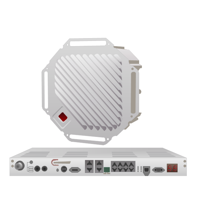
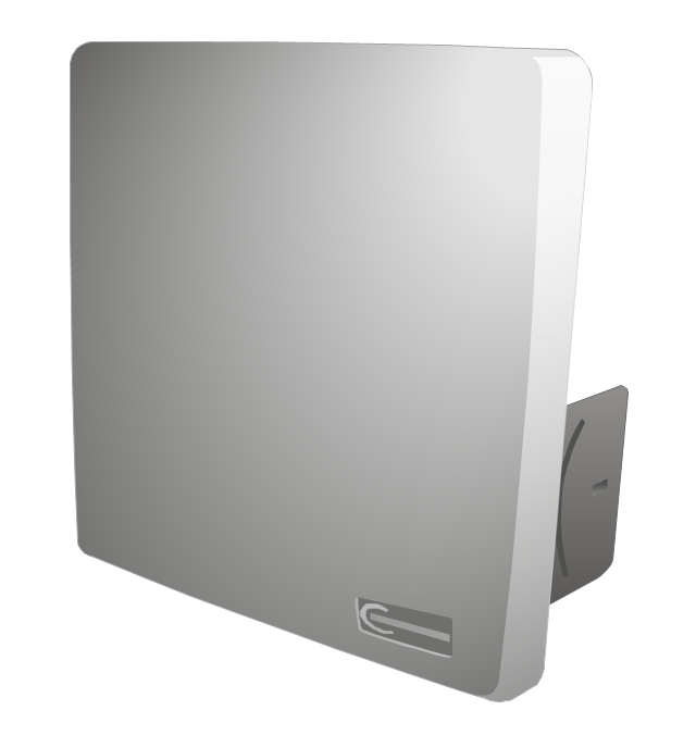
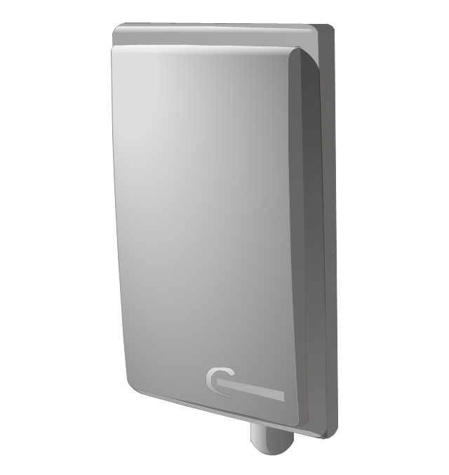
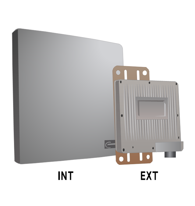
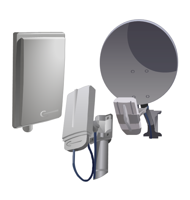
The vector stencils library "Trango" contains 10 clipart icons of Trango devices for drawing computer network diagrams and telecommunication equipment layouts.
"Trango Systems, Inc., was founded in 1996 and is headquartered in San Diego County, California. ...
Trango Systems microwave backhaul solutions and products are used in cellular/ mobile backhaul, Enterprise LAN/ WAN Bridging, All-IP Service Provider Networks, and Government/ Municipal applications." [trangosys.com]
The clip art example "Trango - Vector stencils library" was created using the ConceptDraw PRO diagramming and vector drawing software extended with the Telecommunication Network Diagrams solution from the Computer and Networks area of ConceptDraw Solution Park.
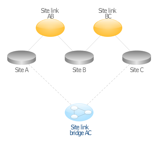
This AD diagram example was redesigned from the picture "Site links" from the book "Active Directory for Dummies".
"Site links represent the Active Directory replication paths between sites.
These paths are manually defined so that the designer has control over which network links the replication traffic occurs on. These site links also control how clients are directed to domain controllers when there’s no DC in the client’s local site. Each site link has the following attributes:
(1) Connected sites: A site link is defined by the sites to which it connects. A site link can connect two or more sites together.
(2) Network transport: Site links support replication communication over IP-based RPCs or with the Simple Mail Transport Protocol (SMTP). You normally want to use RPC whenever possible, but you can use SMTP when the sites you’re linking don’t support RPC.
(3) Cost: Each site link has a cost associated with it. Costs are used to assign preferences to links that determine which link should be followed when multiple link paths are available between sites. The cost represents what it “costs” to use this site link relative to the other site links and affects replication traffic as well as how users are assigned a domain controller. Links with lower cost values have preference over links with higher cost values. Cost values range from 1–32,767; the default being 100.
(4) Frequency: The frequency value defines how often a replication occurs
when using this site link (the replication latency). You can configure the time between replications from a minimum of 15 minutes to a maximum of 10,080 minutes (one week). The default frequency is 180 minutes.
(5) Schedule: The schedule dictates when this link is active and available for replication between the sites. The schedule can also control which days of the week the link is available. Normally, the schedule is set so that the link is available 24 hours a day, but you can set up different schedules on a per-day-of-the-week basis.
By creating a site link, you enable two or more sites to be connected and to share the same site link attributes (transport, cost, frequency, and schedule). By default, site links create transitive connectivity between sites.
If you create a site link between sites A and B and another site link between
sites B and C, an automatic connection (known as a site link bridge) is created between sites A and C..." [Steve Clines and Marcia Loughry, Active Directory® For Dummies®, 2nd Edition. 2008]
The Active Directory diagram example "Site links" was created using the ConceptDraw PRO diagramming and vector drawing software extended with the Active Directory Diagrams solution from the Computer and Networks area of ConceptDraw Solution Park.
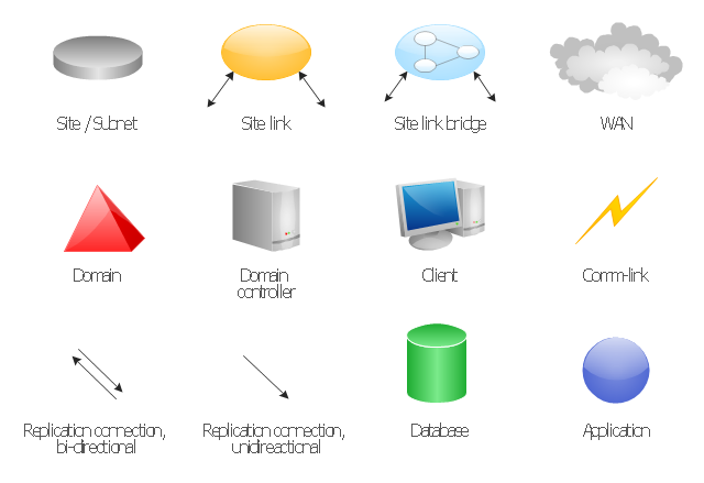
The vector stencils library "Active Directory Sites and Services" contains 12 symbol icons for drawing AD network topology diagrams.
"Active Directory® Sites and Services is a Microsoft Management Console (MMC) snap-in that you can use to administer the replication of directory data among all sites in an Active Directory Domain Services (AD DS) forest. This snap-in also provides a view of the service-specific objects that are published in AD DS. ...
Administrators who are responsible for forest-wide service administration can use Active Directory Sites and Services to manage the intersite replication topology for the forest. Administrators who are responsible for application services can be delegated responsibility for the service containers into which application-specific objects are published." [technet.microsoft.com/ en-us/ library/ cc730868.aspx]
The shapes example "Design elements - Active Directory Sites and Services" for the ConceptDraw PRO diagramming and vector drawing software is icluded in the Active Directory Diagrams solution from the Computer and Networks area of ConceptDraw Solution Park.
- Cisco Network Design. Cisco icons , shapes, stencils, symbols and ...
- Cisco Routers. Cisco icons , shapes, stencils and symbols | Cisco ...
- Cisco Network Topology. Cisco icons , shapes, stencils and symbols ...
- Cisco Network Topology. Cisco icons , shapes, stencils and symbols ...
- Cisco Telepresence. Cisco icons , shapes, stencils and symbols ...
- Network Icon | Network Architecture | Metropolitan area networks ...
- Network Icon | Local area network (LAN). Computer and Network ...
- Cisco - Vector stencils library | Computer and Networks Area ...
- Network Icon | Network Topologies | Network Configuration ...
- Wireless router network diagram | What Is a Wireless Network ...
- Network Icon | Design elements - Network layout floorplan | Local ...
- How To use Switches in Network Diagram | Computer network ...
- Wireless access point - Network diagram | Cisco - Vector stencils ...
- How To use Switches in Network Diagram | Cisco Switches and ...
- Network Gateway Router | Computer Network Diagrams | Diagram ...
- Computer Network Diagrams | Logical network diagram - Vector ...
- Network Icon | Network Diagram Software Home Area Network | Pan ...
- Cisco Network Topology. Cisco icons , shapes, stencils and symbols ...
- Cisco Multimedia, Voice, Phone. Cisco icons , shapes, stencils and ...
- Network Diagramming Software for Design Cisco Network Diagrams ...



-cisco---vector-stencils-library.png--diagram-flowchart-example.png)
-cisco---vector-stencils-library.png--diagram-flowchart-example.png)
-cisco---vector-stencils-library.png--diagram-flowchart-example.png)
-cisco---vector-stencils-library.png--diagram-flowchart-example.png)
-cisco---vector-stencils-library.png--diagram-flowchart-example.png)
-cisco---vector-stencils-library.png--diagram-flowchart-example.png)
-cisco---vector-stencils-library.png--diagram-flowchart-example.png)
-cisco---vector-stencils-library.png--diagram-flowchart-example.png)
-cisco---vector-stencils-library.png--diagram-flowchart-example.png)
-cisco---vector-stencils-library.png--diagram-flowchart-example.png)
-cisco---vector-stencils-library.png--diagram-flowchart-example.png)
-cisco---vector-stencils-library.png--diagram-flowchart-example.png)
-cisco---vector-stencils-library.png--diagram-flowchart-example.png)


-cisco-network-topology---vector-stencils-library.png--diagram-flowchart-example.png)
-cisco-network-topology---vector-stencils-library.png--diagram-flowchart-example.png)


-cisco-network-topology---vector-stencils-library.png--diagram-flowchart-example.png)


-cisco-network-topology---vector-stencils-library.png--diagram-flowchart-example.png)


-cisco-network-topology---vector-stencils-library.png--diagram-flowchart-example.png)


-logical-symbols---vector-stencils-library.png--diagram-flowchart-example.png)


