Process Flow Diagram Symbols

Technical Drawing Software

The vector stencils library "Machines and equipment" contains 24 symbols of industrial machines and equipment.
Use the design elements library "Machines and equipment" for drawing plant interior design plans, manufacturing equipment layouts and factory floor plans using the ConceptDraw PRO diagramming and vector drawing software.
"Manufacturing is the production of goods for use or sale using labor and machines, tools, chemical and biological processing, or formulation. The term may refer to a range of human activity, from handicraft to high tech, but is most commonly applied to industrial production, in which raw materials are transformed into finished goods on a large scale.
Modern manufacturing includes all intermediate processes required for the production and integration of a product's components. Some industries, such as semiconductor and steel manufacturers use the term fabrication instead.
The manufacturing sector is closely connected with engineering and industrial design." [Manufacturing. Wikipedia]
The shapes library "Machines and equipment" is included in the Plant Layout Plans solution from the Building Plans area of ConceptDraw Solution Park.
Machines and equipment symbols

Building Drawing Software for Designing Plumbing


How Do Fishbone Diagrams Solve Manufacturing Problems

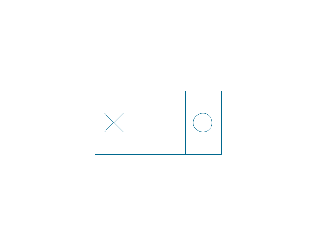
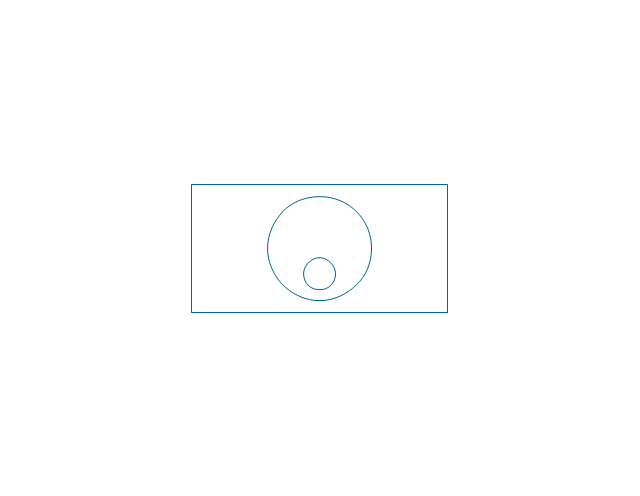
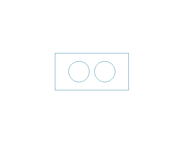
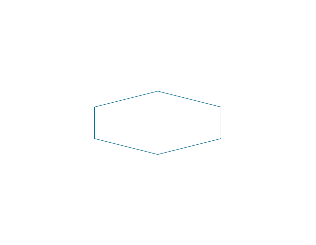
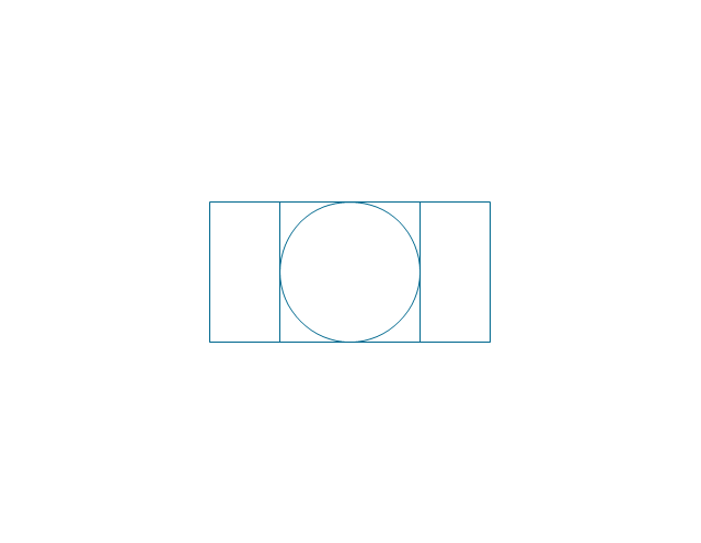
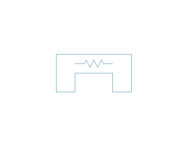
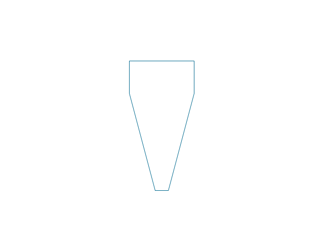
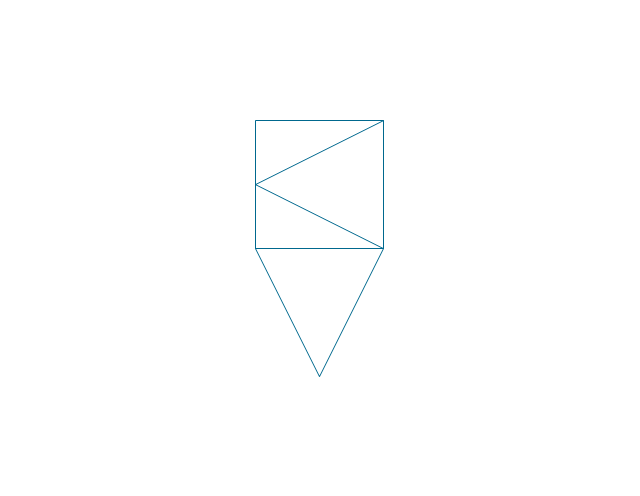
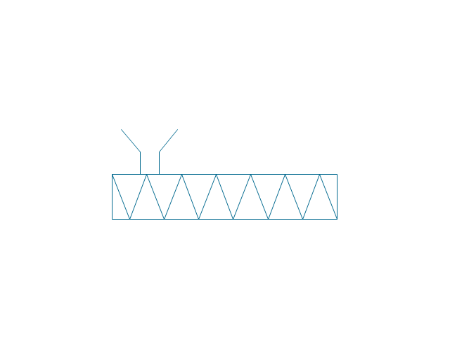
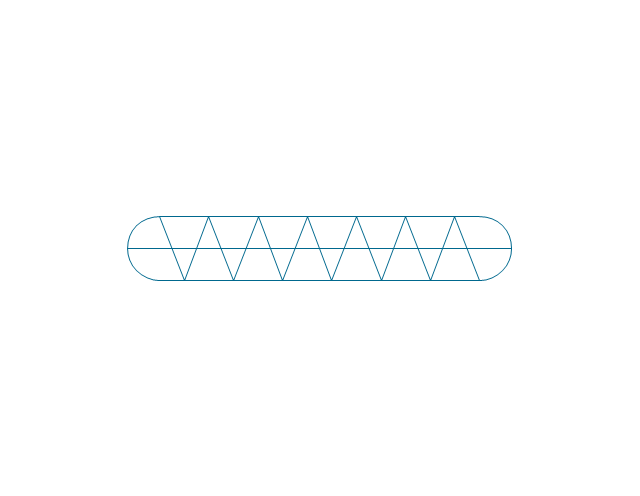
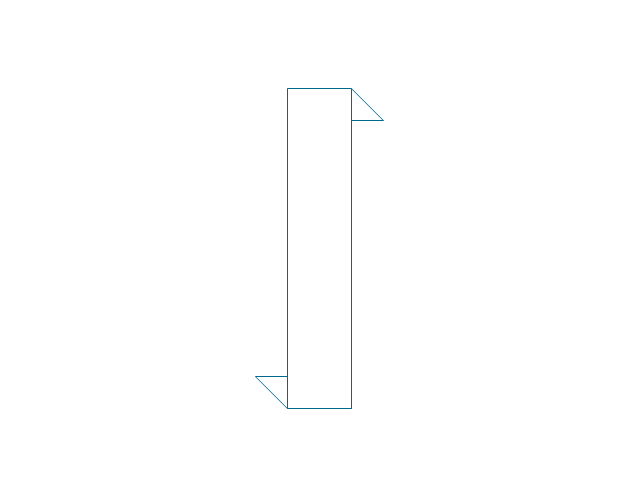
The vector stencils library "Industrial equipment" contains 81 symbols of pumps, compressors, fans, turbines, and power generators.
Use these shapes to design pumping systems, air and fluid compression systems, and industrial process diagrams in the ConceptDraw PRO software extended with the Chemical and Process Engineering solution from the Chemical and Process Engineering area of ConceptDraw Solution Park.
www.conceptdraw.com/ solution-park/ engineering-chemical-process
Breaker
Crusher
Crusher coarse
Crusher medium
Crusher fine

Roll crusher

Hammer crusher

Crusher single load
Crusher hammer

Crusher impact
Crusher jaw

Crusher high-speed roller

Crusher cone

Crusher cone 2
Crusher general
Crusher hammer 2
Crusher impact 2
Crusher jaw 2
Crusher roller
Ball mill

Mill general

Mill hammer
Mill impact
Mill jet
Mill roller
Mill vibrator

Mixer

Mixer general
Mixer rotary
Mixer can
Mixer fluidized

Kneader

Kneader general
Kneader wheel
Kneader ball
Kneader rolling
Kneader blade

Blender

Double blender
Fluid separator general

Fluid separator wet

Fluid separator dry

Fluid separator gravitation

Fluid separator inertial

Fluid separator centrifugal

Filter 1
Filter 2

Rotary filter

Screen

Electromagnet
Cyclone 1
Cyclone 2
Centrifuge general
Centrifuge dehydrator
Centrifuge submersion
Centrifuge 2

Briquetting machine standard
Briquetting machine

Prill tower

Dryer

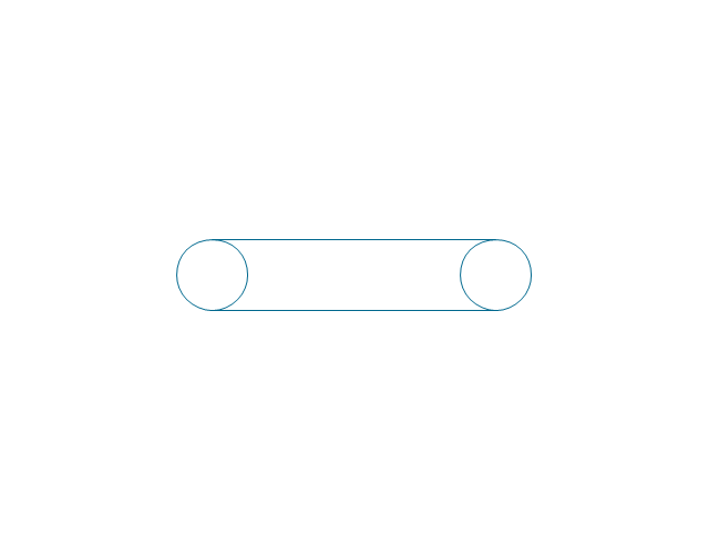
Conveyor 2 circles 2 lines
Conveyor 2 circles 1 line

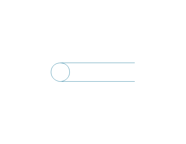
Conveyor 1 circle 2 lines
Conveyor 1 circle 1 line

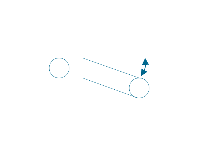
Conveyor wheel

Boom loader
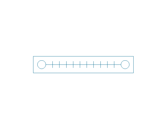
Scraper conveyor
Screw conveyor
Screw conveyor 2
Elevator 1
Elevator 2

Skip hoist

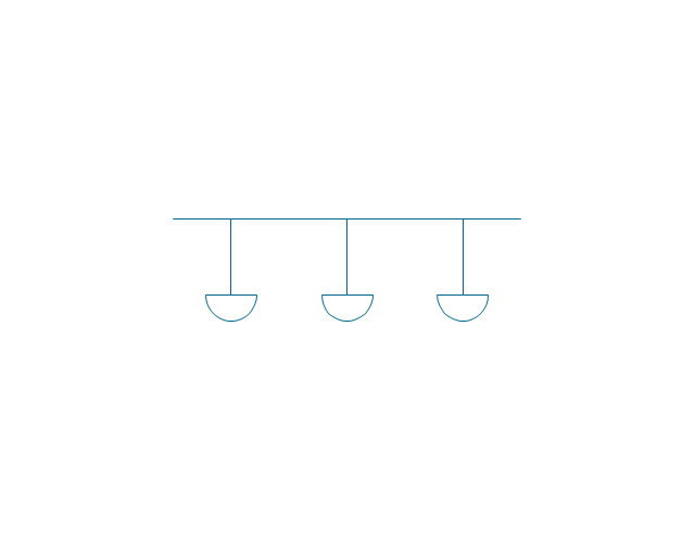
Overhead conveyor

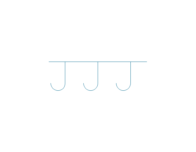
Overhead conveyor with hooks
Overhead conveyor with buckets
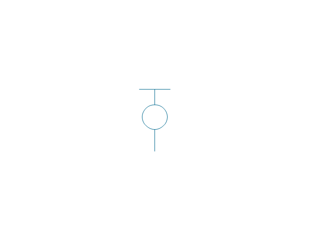
Hoist
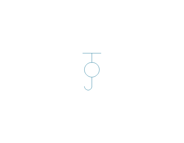
Hoist with hook
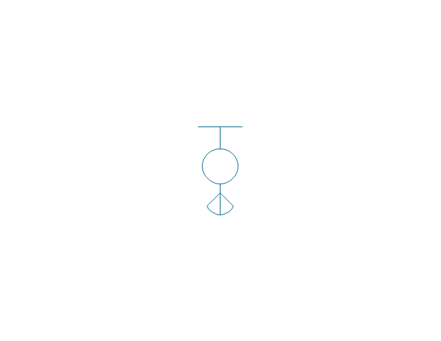
Hoist with grab
Electric motor
Tank truck

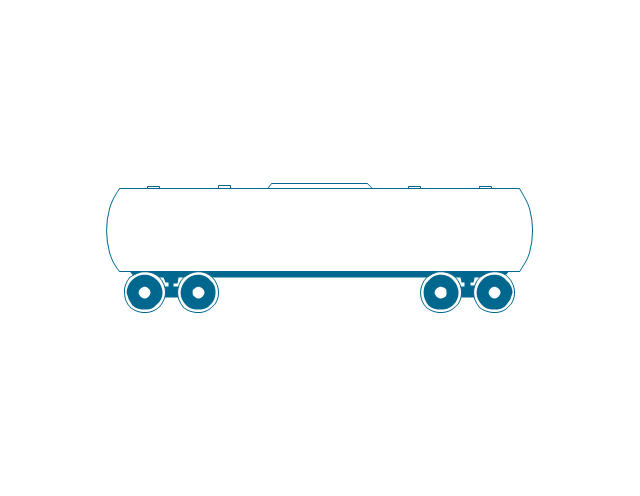
Tank car
 Plant Layout Plans
Plant Layout Plans solution can be used for power plant design and plant layout design, for making the needed building plant plans and plant layouts looking professionally good. Having the newest plant layout software, the plant design solutions and in particular the ConceptDraw’s Plant Layout Plans solution, including the pre-made templates, examples of the plant layout plans, and the stencil libraries with the design elements, the architects, electricians, interior designers, builders, telecommunications managers, plant design engineers, and other technicians can use them to create the professionally looking drawings within only a few minutes.
Process Flowchart


Piping and Instrumentation Diagram Software

- Design elements - Industrial equipment | Chemical and Process ...
- Equipment And Their Symbols Used In Chemical Industries
- Design elements - Machines and equipment | Plant Layout Plans ...
- Design elements - Industrial equipment | Design elements ...
- Design elements - Industrial equipment | Chemical and Process ...
- Design elements - Machines and equipment | Symbol Drawing Used ...
- Design elements - Industrial equipment | Process Flow Diagram ...
- Design elements - Machines and equipment | Design elements ...
- Design elements - Industrial equipment | Design elements ...