ConceptDraw DIAGRAM Database Modeling Software

Entity Relationship Diagram Symbols

ERD Symbols and Meanings


Software development with ConceptDraw DIAGRAM

Data structure diagram with ConceptDraw DIAGRAM

ER diagram tool for OS X
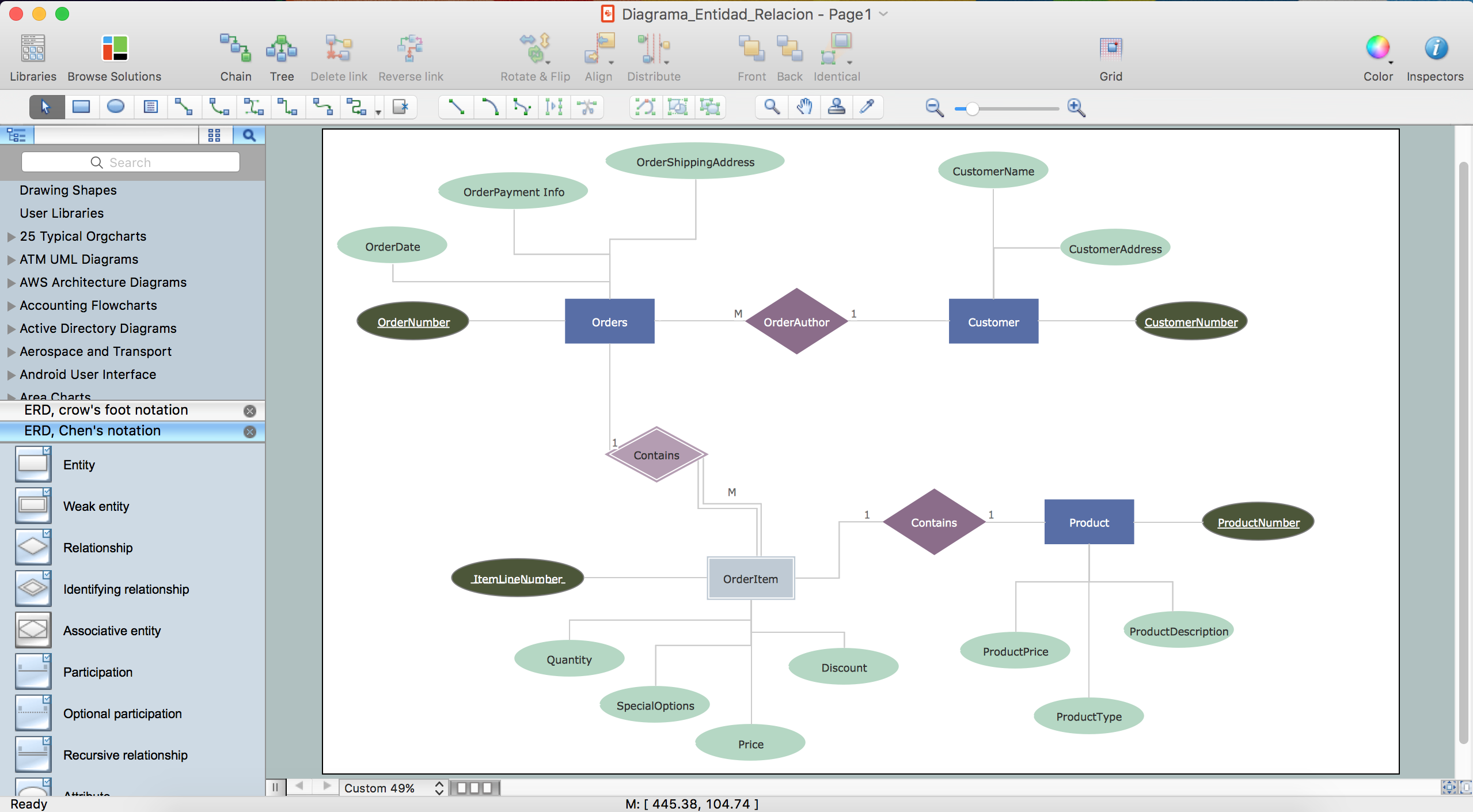
 Entity-Relationship Diagram (ERD)
An Entity-Relationship Diagram (ERD) is a visual presentation of entities and relationships. That type of diagrams is often used in the semi-structured or unstructured data in databases and information systems. At first glance ERD is similar to a flowch
Cisco Routers. Cisco icons, shapes, stencils and symbols

Diagramming Software for Design UML Object Diagrams


Garrett IA Diagrams with ConceptDraw DIAGRAM

- Electrical Symbols, Electrical Diagram Symbols | Design elements ...
- Table In Db Symble
- Supermarket Management System Project Db Diagram
- Venn Diagram Examples for Problem Solving . Quantum Information ...
- Half Pipe Plans | Design elements - Appliances | Plumbing and ...
- Entity Relationship Diagram Examples | Property Management ...
- Half Pipe Plans | Create Floor Plan | Plumbing and Piping Plans ...
- Electrical Db Design Video Dawunlod
- Electrical Symbols, Electrical Diagram Symbols | Design elements ...
- Flowchart Marketing Process. Flowchart Examples | Content ...