 Plumbing and Piping Plans
Plumbing and Piping Plans solution extends ConceptDraw PRO v10.2.2 software with samples, templates and libraries of pipes, plumbing, and valves design elements for developing of water and plumbing systems, and for drawing Plumbing plan, Piping plan, PVC Pipe plan, PVC Pipe furniture plan, Plumbing layout plan, Plumbing floor plan, Half pipe plans, Pipe bender plans.
 Mechanical Engineering
This solution extends ConceptDraw PRO v.9 mechanical drawing software (or later) with samples of mechanical drawing symbols, templates and libraries of design elements, for help when drafting mechanical engineering drawings, or parts, assembly, pneumatic,
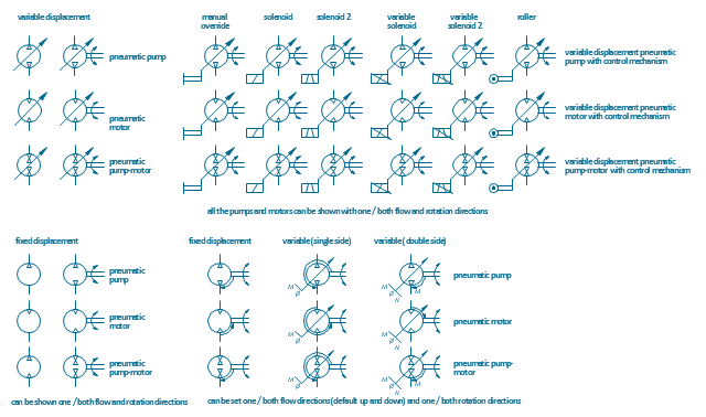
The vector stencils library "Pneumatic pumps and motors" contains 39 symbols of pneumatic pumps, motors and pump-motors for designing the engineering drawings of pneumatic circuits.
"A pneumatic motor or compressed air engine is a type of motor which does mechanical work by expanding compressed air. Pneumatic motors generally convert the compressed air energy to mechanical work through either linear or rotary motion. Linear motion can come from either a diaphragm or piston actuator, while rotary motion is supplied by either a vane type air motor or piston air motor." [Pneumatic motor. Wikipedia]
"A gas compressor is a mechanical device that increases the pressure of a gas by reducing its volume. An air compressor is a specific type of gas compressor.
Compressors are similar to pumps: both increase the pressure on a fluid and both can transport the fluid through a pipe. As gases are compressible, the compressor also reduces the volume of a gas. Liquids are relatively incompressible; while some can be compressed, the main action of a pump is to pressurize and transport liquids." [Gas compressor. Wikipedia]
The shapes example "Design elements - Pneumatic pumps and motors" was created using the ConceptDraw PRO diagramming and vector drawing software extended with the Mechanical Engineering solution from the Engineering area of ConceptDraw Solution Park.
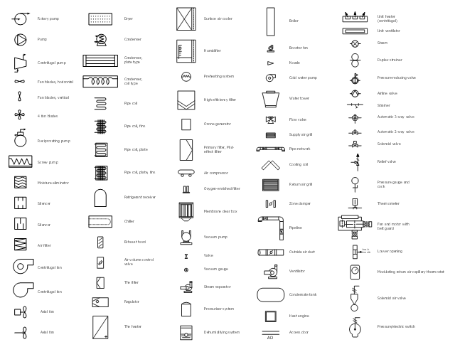
The vector stencils library "HVAC equipment" contains 26 symbols of HVAC equipment as pumps, fans, condensers, pipe coils, silencers, etc.
Use the design elements library "HVAC equipment" for drawing the HVAC system diagrams, heating, ventilation, air conditioning, refrigeration, automated building control and environmental control system layout floor plans using the ConceptDraw PRO diagramming and vector drawing software.
"HVAC (heating, ventilation, and air conditioning) is the technology of indoor and vehicular environmental comfort. HVAC system design is a subdiscipline of mechanical engineering, based on the principles of thermodynamics, fluid mechanics, and heat transfer. Refrigeration is sometimes added to the field's abbreviation as HVAC&R or HVACR, or ventilating is dropped as in HACR (such as the designation of HACR-rated circuit breakers).
HVAC is important in the design of medium to large industrial and office buildings such as skyscrapers and in marine environments such as aquariums, where safe and healthy building conditions are regulated with respect to temperature and humidity, using fresh air from outdoors." [HVAC. Wikipedia]
The shapes library "HVAC equipment" is contained in the HVAC Plans solution from the Building Plans area of ConceptDraw Solution Park.
 ConceptDraw Solution Park
ConceptDraw Solution Park collects graphic extensions, examples and learning materials
 Chemical and Process Engineering
This chemical engineering solution extends ConceptDraw PRO v.9.5 (or later) with process flow diagram symbols, samples, process diagrams templates and libraries of design elements for creating process and instrumentation diagrams, block flow diagrams (BFD
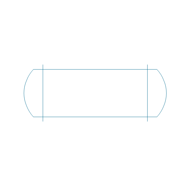
The vector stencils library "Heating equipment" contains 42 symbols of regenerators, intercoolers, heaters, and condensers.
Use these shapes for drawing cooling systems, heat recovery systems, thermal, heat transfer and mechanical design, and process flow diagrams (PFD) in the ConceptDraw PRO software extended with the Chemical and Process Engineering solution from the Chemical and Process Engineering area of ConceptDraw Solution Park.
www.conceptdraw.com/ solution-park/ engineering-chemical-process
 Physics
Physics solution extends ConceptDraw PRO software with templates, samples and libraries of vector stencils for drawing the physical illustrations, diagrams and charts.
 Chemistry
This solution extends ConceptDraw PRO software with samples, template and libraries of vector stencils for drawing the Chemistry Illustrations for science and education.
 Computer and Networks Area
The solutions from Computer and Networks Area of ConceptDraw Solution Park collect samples, templates and vector stencils libraries for drawing computer and network diagrams, schemes and technical drawings.
 HVAC Plans
Use HVAC Plans solution to create professional, clear and vivid HVAC-systems design plans, which represent effectively your HVAC marketing plan ideas, develop plans for modern ventilation units, central air heaters, to display the refrigeration systems for automated buildings control, environmental control, and energy systems.
 Active Directory Diagrams
Active Directory Diagrams solution extends ConceptDraw PRO software with samples, templates and libraries of vector stencils for drawing the AD diagrams to visualize the detail structures of the Microsoft Windows networks.
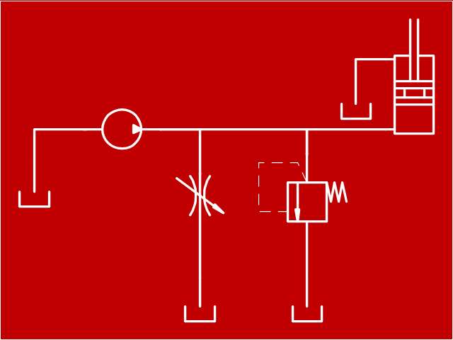
"Hydraulics is a topic in applied science and engineering dealing with the mechanical properties of liquids. At a very basic level hydraulics is the liquid version of pneumatics. Fluid mechanics provides the theoretical foundation for hydraulics, which focuses on the engineering uses of fluid properties. In fluid power, hydraulics is used for the generation, control, and transmission of power by the use of pressurized liquids. Hydraulic topics range through some part of science and most of engineering modules, and cover concepts such as pipe flow, dam design, fluidics and fluid control circuitry, pumps, turbines, hydropower, computational fluid dynamics, flow measurement, river channel behavior and erosion." [Hydraulics. Wikipedia]
This hydraulic schematic example was redrawn using ConceptDraw PRO diagramming and vector drawing software from the Wikimedia Commons file: Skjematikk.GIF.
[commons.wikimedia.org/ wiki/ File:Skjematikk.GIF]
This file is licensed under the Creative Commons Attribution-Share Alike 3.0 Unported license.
[creativecommons.org/ licenses/ by-sa/ 3.0/ deed.en]
The engineering drawing example "Hydraulic schematic" was created using the ConceptDraw PRO diagramming and vector drawing software extended with the Mechanical Engineering solution from the Engineering area of ConceptDraw Solution Park.
- Piping and Instrumentation Diagram Software | Design elements ...
- Mechanical Drawing Symbols | Piping and Instrumentation Diagram ...
- Mechanical Engineering | Mechanical Drawing Symbols | Interior ...
- Mechanical Engineering | Interior Design Piping Plan - Design ...
- Mechanical Drawing Symbols | Mechanical Engineering | Piping ...
- Interior Design Piping Plan - Design Elements | Mechanical Drawing ...
- Mechanical Drawing Symbols | Interior Design Piping Plan - Design ...
- Drafting Symbols For Valves
- Interior Design Piping Plan - Design Elements | Mechanical Drawing ...
- Mechanical Drawing Symbols | Interior Design Piping Plan - Design ...
- Welding symbols | Mechanical Engineering | Design elements ...
- Mechanical Engineering | Pipe Welding Symbols Chart
- Interior Design Piping Plan - Design Elements | Mechanical ...
- Basic Mechanical Piping Symbols
- Mechanical Drawing Symbols | Mechanical Engineering | Elements ...
- Mechanical Engineering | Pipe Welding Symbols Pdf
- How To Draw Building Plans | Piping and Instrumentation Diagram ...
- Engineering | Mechanical Engineering | Interior Design Piping Plan ...
- Building Drawing Design Element: Piping Plan | Plumbing and ...
- Valve Symbols
















-heating-equipment---vector-stencils-library.png--diagram-flowchart-example.png)



-heating-equipment---vector-stencils-library.png--diagram-flowchart-example.png)
-heating-equipment---vector-stencils-library.png--diagram-flowchart-example.png)
-heating-equipment---vector-stencils-library.png--diagram-flowchart-example.png)
-heating-equipment---vector-stencils-library.png--diagram-flowchart-example.png)
-heating-equipment---vector-stencils-library.png--diagram-flowchart-example.png)
-heating-equipment---vector-stencils-library.png--diagram-flowchart-example.png)
-heating-equipment---vector-stencils-library.png--diagram-flowchart-example.png)
-heating-equipment---vector-stencils-library.png--diagram-flowchart-example.png)


-heating-equipment---vector-stencils-library.png--diagram-flowchart-example.png)


