 Mechanical Engineering
This solution extends ConceptDraw DIAGRAM.9 mechanical drawing software (or later) with samples of mechanical drawing symbols, templates and libraries of design elements, for help when drafting mechanical engineering drawings, or parts, assembly, pneumatic,
HelpDesk
How to Create a Mechanical Diagram
Mechanical Engineering drawing is a type of technical drawing that helps analyze complex engineering systems. Mechanical Engineering diagrams are often a set of detailed drawings used for engineering or construction projects. Making Mechanical Engineering diagram involves many different elements that can be managed using ConceptDraw DIAGRAM. You can design elements for drawing parts, assembly, pneumatic, and hydraulic systems for mechanical engineering. With ConceptDraw DIAGRAM you can easily create and communicate the Mechanical Engineering diagram of any complexity.Network Diagram Software
Network Diagrams are used to visually represent the network architecture, to illustrate the network structure, how the computers and other elements of the network are connected each other using a variety of network symbols, clipart and connection lines. They are incredibly useful on the stages of projecting computer network, of its construction and exploitation. Professionally designed and accurate Network Diagrams are equally convenient for computer engineers and users. You can construct them by hand on the paper or use special network diagramming software, such as ConceptDraw DIAGRAM. Having at disposal the powerful network diagramming tools of Computer Network Diagrams solution included to ConceptDraw Solution Park, you can succeed in drawing various types of Computer Network Diagrams, among them Network Communication Plans, Logical Network Diagrams, Network Topology Diagrams, LAN and WAN Diagrams, Network Floor Plan Layouts, Computer Network System Diagrams, Web-based Network Diagrams, Wireless Network Diagrams, Cisco Network Diagram, and others.
HelpDesk
How to Create an Electrical Diagram
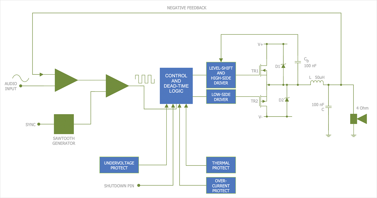
There are many different electric circuit symbols that can be used in a circuit diagram. Knowing how to read circuit diagrams is a useful skill not only for professionals but for any person who can start creating his own small home electronic projects. The circuit diagram shows the scheme of a location of components and connections of the electrical circuit using a set of standard symbols. It can be used for graphical documentation of electrical circuit components. The ability to create electrical diagrams and schematic using ConceptDraw DIAGRAM is delivered by the Electrical Engineering solution. The solution supplied with samples, templates, and libraries of design elements for drawing electrical schematics, digital and analog logic, circuit and wiring schematics and diagrams, power systems diagrams, maintenance and repair diagrams for electronics and electrical engineering.- Mechanical Drawing Symbols | Mechanical Engineering | Process ...
- Mechanical Engineering Drawings Samples
- Mechanical Drawing Symbols | Mechanical Drawing Software ...
- Sample Of Building Mechanical Drawing
- Industrial Drawing Sample Pdf
- Mechanical Product Drawing Example
- Technical Drawing Sample For Mechanical Engineering
- Mechanical Drawing Symbols | Process Flowchart | Mechanical ...
- Mechanical Components Drawing Samples
- Mechanical Engineering | Mechanical Drawing Symbols | Technical ...
- Mechanical Drawing Symbols | Mechanical Engineering ...
- Technical drawing - Machine parts assembling | Mechanical ...
- Mechanical Assembly Drawing Sample
- How To Draw A Mechanical Engineering Schematics
- Example Of Application Of Technical Drawing For Mechanical
- Examples Of Building Mechanical Drawings
- Mechanical Drawing Samples
- Samples Of Technical Drawings In Pdf Format
- Design elements - Bearings | Mechanical Drawing Symbols ...
- Examples Of Layout Part Drawings In Technical Drawing


