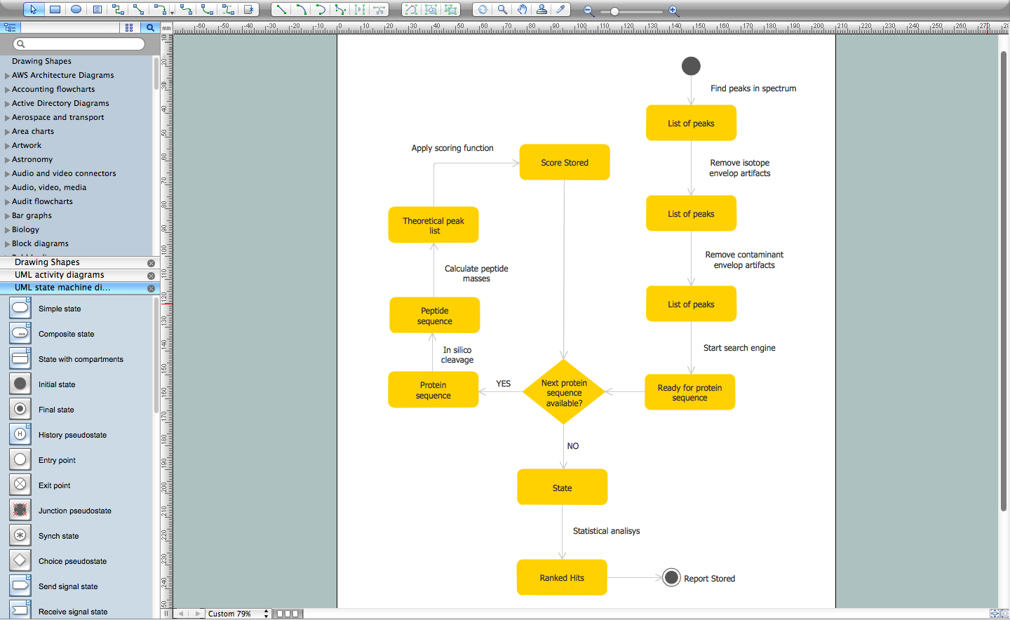
State Diagram Example — Online Store
This sample was created in ConceptDraw DIAGRAM diagramming and vector drawing software using the UML State Mashine Diagram library of the Rapid UML Solution from the Software Development area of ConceptDraw Solution Park. This sample shows the work of the online store and can be used for the understanding of the online shopping processes, for projection and creating of the online store.UML Diagram for Mac
This sample was created on the Mac in ConceptDraw DIAGRAM diagramming and vector drawing software using the UML State Machine Diagram library of the Rapid UML Solution from the Software Development area of ConceptDraw Solution Park.ERD Symbols and Meanings
Entity Relationship Diagram (ERD) is a popular software engineering tool for database modeling and illustration the logical structure of databases, which uses one of two notations - Chen's or Crow’s Foot. Crow's foot notation is effective when used in software engineering, information engineering, structured systems analysis and design. Each of these notations applies its own set of ERD symbols. Crow's foot diagrams use boxes to represent entities and lines between these boxes to show relationships. Varied shapes at the ends of lines depict the cardinality of a given relationship. Chen's ERD notation is more detailed way to represent entities and relationships. ConceptDraw DIAGRAM application enhanced with all-inclusive Entity-Relationship Diagram (ERD) solution allows design professional ER diagrams with Chen's or Crow’s Foot notation on your choice. It contains the full set of ready-to-use standardized ERD symbols and meanings helpful for quickly drawing, collection of predesigned ERD samples, examples and templates. ConceptDraw Pro is a great alternative to Visio for Mac users as it offers more features and can easily handle the most demanding professional needs.
UML Notation
Unified Modeling Language (UML) is an open standard, the language of graphic description used for modeling objects in a field of software development and software engineering. It was created for definition, specification, visualization, designing and documenting software systems, as a unification of three object-oriented technologies Booch, OMT and OOSE, and uses the defined graphic notation for creating the visual models of object-oriented software systems. Description of UML consists of two parts, interactive and supplementing each other: UML semantics, which represents a certain metamodel, defines the abstract syntax and semantics of terms of object modeling with UML, and UML notation that is a graphic notation for visual representation of UML semantics. The powerful tools of the Rapid UML solution included to ConceptDraw Solution Park make the ConceptDraw DIAGRAM diagramming and vector drawing software the best for easy applying the UML notation when creating the visual models of object-oriented software systems and designing different kinds of UML diagrams.- Export from ConceptDraw MINDMAP to PowerPoint® Presentation ...
- Concept Map Maker | Mind Map Making Software | Quality ...
- Nursing Concept Map Generator
- Concept Map Creator
- Concept Map | Simple Diagramming | Concept Maps | Concept Map ...
- How To Create Good Presentation Ideas | Presenting Documents ...
- Concept Map Of Production
- Atmosphere air composition | Percentage Pie Chart. Pie Chart ...
- Process Flowchart | Basic Flowchart Symbols and Meaning | Flow ...
- Ishikawa Diagram | How to Create a Fishbone (Ishikawa) Diagram ...
- What is Value Stream Mapping ?
- Process Flowchart | Basic Flowchart Symbols and Meaning | Types ...
- Ishikawa Diagram | How to Create a Fishbone (Ishikawa) Diagram ...
- Example of DFD for Online Store (Data Flow Diagram) DFD ...
- Basic Flowchart Symbols and Meaning | Process Flowchart | Audit ...
- State Diagram Example - Online Store | How to Use the ″Online ...
- Purchasing Flowchart - Purchase Order. Flowchart Examples | Steps ...
- How to Diagram Sentences in ConceptDraw PRO | Sentence ...
- Material Requisition Flowchart. Flowchart Examples | Value stream ...
- Process Flowchart | Basic Flowchart Symbols and Meaning ...


