This reflected ceiling plan example shows the lighting scheme of computer lab with overhead projector. It was drawn on the base of the RCP from website of Elon University, Elon, NC.
[elon.edu/ docs/ e-web/ bft/ cmdept/ Reflected%20 Ceiling.JPG]
"An overhead projector is a variant of slide projector that is used to display images to an audience. ...
Use in education.
The overhead projector facilitates an easy low-cost interactive environment for educators. Teaching materials can be pre-printed on plastic sheets, upon which the educator can directly write using a non-permanent, washable color marking pen. This saves time, since the transparency can be pre-printed and used repetitively, rather than having materials written manually before each class.
The overhead is typically placed at a comfortable writing height for the educator and allows the educator to face the class, facilitating better communication between the students and teacher. The enlarging features of the projector allow the educator to write in a comfortable small script in a natural writing position rather than writing in an overly large script on a blackboard and having to constantly hold his arm out in midair to write on the blackboard.
When the transparency sheet is full of written or drawn material, it can simply be replaced with a new, fresh sheet with more pre-printed material, again saving class time vs a blackboard that would need to be erased and teaching materials rewritten by the educator. Following the class period, the transparencies are easily restored to their original unused state by washing off with soap and water." [Overhead projector. Wikipedia]
The classroom reflected ceiling plan example "Computer lab RCP" was created using the ConceptDraw DIAGRAM diagramming and vector drawing software extended with the Reflected Ceiling Plans solution from the Building Plans area of ConceptDraw Solution Park.
Local network area. Computer and Network Examples
A Local Area Network (LAN) is a computer network that interconnects computers on the limited area such as a home, office building, school, bank, computer laboratory, etc. ConceptDraw DIAGRAM is a powerful network diagramming and vector drawing software. It provides the Computer and Networks Area with many Solutions that contain the wide set ready-to-use predesigned vector stencils and examples to help you design the LANs quick and easy.Computer Network Diagrams
Computer Network Diagrams solution extends ConceptDraw DIAGRAM software with samples, templates and libraries of vector icons and objects of computer network devices and network components to help you create professional-looking Computer Network Diagrams, to plan simple home networks and complex computer network configurations for large buildings, to represent their schemes in a comprehensible graphical view, to document computer networks configurations, to depict the interactions between network's components, the used protocols and topologies, to represent physical and logical network structures, to compare visually different topologies and to depict their combinations, to represent in details the network structure with help of schemes, to study and analyze the network configurations, to communicate effectively to engineers, stakeholders and end-users, to track network working and troubleshoot, if necessary.
Rack Diagrams
The Rack Diagrams solution can be used while working in the ConceptDraw DIAGRAM diagramming and drawing software in order to create the necessary Rack diagrams. Choosing any of the 54 vector shapes from its stencil library, you can use the Rack Diagrams solution for drawing various types of Rack diagrams or Server rack diagrams visualizing 19" rack mounted computers and servers. The Rack Diagrams solution, additionally including a collection of samples and a quick-start template, can be useful for many users of the ConceptDraw DIAGRAM who deal with computer networks, such as IT specialists; computer, network and telecommunication engineers; software engineers, technical writers, IT managers, system administrators, technical support, webmasters, system architects and engineers.
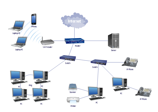
"A local area network (LAN) is a computer network that interconnects computers in a limited area such as a home, school, computer laboratory, or office building using network media. The defining characteristics of LANs, in contrast to wide area networks (WANs), include their smaller geographic area, and non-inclusion of leased telecommunication lines. Ethernet over twisted pair cabling, and Wi-Fi are the two most common technology standards currently used to build LANs." [Local area network. Wikipedia]
This local area network (LAN) topology diargam example was created using the ConceptDraw PRO diagramming and vector drawing software extended with the Computer and Networks solution from the Computer and Networks area of ConceptDraw Solution Park.
The vector stencils library "Computer network" contains 51 symbols of computer network devices and equipment for drawing computer network diagrams.
"Network Mapping Software.
A number of software tools exist to design computer network diagrams / or generate visual maps of networks, servers, storage, services, data centers, and other peripherals. Broadly, there are two types of software tools - those that help create diagrams manually and those that generate them using automated / semi-automated approaches.
Type of Software.
(1) Manual - allows users to design and draw logical and physical topology diagrams by manually placing icons and connections.
(2) Automated - generate topology diagrams / maps by traversing the network and automatically discovering resident devices or by importing network data." [Comparison of network diagram software. Wikipedia]
ConceptDraw PRO is the software for manual design of computer network diagrams. The solutions of the Computer and Networks area in ConceptDraw Solution Park extend ConceptDraw PRO with vector stencils libraries, templates and examples for creating the computer network diagrams.
The symbols example "Computer network - Vector stencils library" was created using the ConceptDraw PRO diagramming and vector drawing software extended with the Computer and Networks solution from the Computer and Networks area of ConceptDraw Solution Park.
www.conceptdraw.com/ solution-park/ computer-and-networks
The vector stencils library "Network layout floorplan" contain 34 symbol icons for drawing computer network floor plans and communication equipment and cabling layouts.
"Networking hardware may also be known as network equipment or computer networking devices. Units which are the last receiver or generate data are called hosts or data terminal equipment.
All these terms refer to devices facilitating the use of a computer network. Specifically, they mediate data in a computer network. ...
Typically, networking hardware includes gateways, routers, network bridges, switches, hubs, and repeaters. But it also includes hybrid network devices such as multilayer switches, protocol converters, bridge routers, proxy servers, firewalls, network address translators, multiplexers, network interface controllers, wireless network interface controllers, modems, ISDN terminal adapters, line drivers, wireless access points, networking cables and other related hardware.
The most common kind of networking hardware today is a copper-based Ethernet adapter because of its standard inclusion on most modern computer systems. Wireless networking has, however, become increasingly popular, especially for portable and handheld devices.
Other hardware prevalent in computer networking includes data center equipment (such as file servers, database servers and storage areas), network services (such as DNS, DHCP, email, etc.) as well as devices which assure content delivery." [Networking hardware. Wikipedia]
The shapes example "Design elements - Network layout floorplan" was created using the ConceptDraw PRO diagramming and vector drawing software extended with the Network Layout Floor Plans solution from the Computer and Networks area of ConceptDraw Solution Park.
What is a Local Area Network? Examples of LAN Diagrams
Local Area Network (LAN) is a network which consists of computers and peripheral devices connected each other and to the local domain server, and covers a little territory or small number of buildings, such as home, school, laboratory, office, etc. LAN serves for few hundreds of users. It includes many cables and wires, and demands to design previously a Network diagram. All local area network devices can use the shared printers and disk storage.
ConceptDraw DIAGRAM is a perfect network diagramming software with examples of LAN Diagrams, templates and predesigned vector objects. ConceptDraw DIAGRAM is the ideal choice for network engineers and network designers who need to draw fast and easy Local Area Network Diagrams, for IT specialists, developers and other IT professionals which need to visualize the communication schemes of LAN and visually document the LAN's physical structure and arrangement in houses, offices and other buildings. Ready-to-use vector objects from Computer Network Diagrams solution will help you design LAN diagrams in minutes.
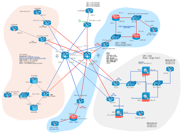
This Cisco network diagram example was drawn on the base of the figure illustrating the post "Cisco Lab 1 : Network Design from the requirement" from the blog "Thai Cisco Club".
"1. Core service porvider by assign P router as P1 and P2, PE router as PE1 - 8 for support CE router of customers.
2. From 1st customer project, assign R1-DMVPN and R2-DWVPN as DMVPN Hub, and R3-DMVPN and R4-DMVPN as DMVPN-Spoke that on different site.
3. From 2nd customer project, assign IP-SEC R1 and IP-SEC R2 as SSO-IP-SEC Router on HQ site, and IP-SEC R3 as branch site that far away."
[thai-cisco-club.blogspot.com/ 2011/ 10/ cisco-lab-1-network-design-from.html]
The diagram example "Cisco network design from the requirement" was created using the ConceptDraw PRO diagramming and vector drawing software extended with the Cisco Network Diagrams solution from the Computer and Networks area of ConceptDraw Solution Park.
This rack diagram example was drawn on the base of picture illustrating the article "Virtualization in general, for technicans and business people" from the Banym's Blog by Dominik Zajac. [banym.de/ virtualization/ virtualization-in-general-for-technicans-and-business-people]
"Virtualization, in computing, refers to the act of creating a virtual (rather than actual) version of something, including but not limited to a virtual computer hardware platform, operating system (OS), storage device, or computer network resources." [Virtualization. Wikipedia]
"With the CPUs we have today you can virtualize up to 10 – 12 old servers to one new big machine with for example 2 x 6 core CPUs and a lot of memory. In this case you see what potential this technology has. Turn off 10 servers and run it on just one machine. That’s not the way I would do Virtualization. It’s nice to save energy but what happens if we have a problem with our one new big server? The complete organization can not work without ERP, EMail etc. and because of this we need a cluster.
Such a cluster configuration looks something like this: (rack diagram example).
Two big servers, a storage subsystem and a smaller management server. If you compare now the old configuration with the new one you can see there will be still made some points for energy efficiency. That’s not the only benefit you should have in focus, for the mature Virtualization solutions like VMware or Citrix/ XEN exist a big number of tools and documentation to make the life easier for administrators and system managers. This safes time and brings better reaction times for your IT." [banym.de/ virtualization/ virtualization-in-general-for-technicans-and-business-people]
The rack diagram example "Virtualized computer center" was created using the ConceptDraw PRO diagramming and vector drawing software extended with the Rack Diagrams solution from the Computer and Networks area of ConceptDraw Solution Park.
Reflected Ceiling Plans
Reflected Ceiling Plans solution extends greatly the ConceptDraw DIAGRAM functionality with samples, templates and libraries of design elements for displaying the ceiling ideas for living room, bedroom, classroom, office, shop, restaurant, and many other premises. It is an effective tool for architects, designers, builders, electricians, and other building-related people to represent their ceiling design ideas and create Reflected Ceiling plan or Reflective Ceiling plan, showing the location of light fixtures, lighting panels, drywall or t-bar ceiling patterns, HVAC grilles or diffusers that may be suspended from the ceiling. Being professional-looking and vivid, these plans perfectly reflect your ceiling ideas and can be presented to the client, in reports, in presentations, on discussions with colleagues, or successfully published in modern print or web editions.
The vector stencils library "Rack diagrams" contains 33 rack design elements for drawing the computer network server rack diagrams.
"A 19-inch rack is a standardized frame or enclosure for mounting multiple equipment modules. Each module has a front panel that is 19 inches (482.6 mm) wide, including edges or ears that protrude on each side which allow the module to be fastened to the rack frame with screws. ...
Equipment designed to be placed in a rack is typically described as rack-mount, rack-mount instrument, a rack mounted system, a rack mount chassis, subrack, rack mountable, or occasionally simply shelf. The height of the electronic modules is also standardized as multiples of 1.75 inches (44.45 mm) or one rack unit or U (less commonly RU). The industry standard rack cabinet is 42U tall. ...
19-inch racks in 2-post or 4-post form hold most equipment in modern data centers, ISP facilities and professionally designed corporate server rooms. They allow for dense hardware configurations without occupying excessive floorspace or requiring shelving." [19-inch rack. Wikipedia]
The clip art example "Rack diagrams - Vector stencils library" was created using the ConceptDraw PRO diagramming and vector drawing software extended with the Rack Diagrams solution from the Computer and Networks area of ConceptDraw Solution Park.
Network Topologies
Network topology is a topological structure of computer network, which can be physical or logical. The physical topology depicts location of different computer network elements such as computers, cables and other devices. The logical topology visually displays network dataflows from one device to another. Sometimes network logical and physical topologies can be the same. ConceptDraw DIAGRAM diagramming and vector drawing software is powerful for drawing network maps and network topologies diagrams of any kinds and complexity thanks to the Computer Network Diagrams solution from the Computer and Networks area. ConceptDraw STORE proposes collection of network icons libraries and a lot of Network Topology Diagram examples, samples and templates which were created at ConceptDraw DIAGRAM software specially for Computer Network Diagrams solution. There are six basic types of the network topologies: Bus, Star, Ring, Mesh, Tree, Fully Connected. You can fast and easy design professional-looking diagram for each of them using the ConceptDraw DIAGRAM tools. There are plenty of web Visio-like diagramming software available. Web based diagrams software can be powerful, but sometimes it is essential to have desktop software. One of the most advanced diagrams tools like Visio for Mac OS is ConceptDraw DIAGRAM app.The Rack
The Rack Diagrams represent the frontal view of the rack with network equipment installed. They are helpful and widely used for choosing the equipment and racks to buy, and give the possibility to visually plan how to organize it on the racks. Now creating of the Rack Diagrams is quite simple and quick thanks to the powerful drawing tools of the Rack Diagrams Solution from the Computer and Networks Area.Chemistry Symbols and Meanings
Chemistry solution offers 5 libraries with large collection of vector chemistry symbols and meanings, chemistry equation symbols, organic chemistry symbols, and chemical clipart: Chemical Elements Library, Chemical Drawings Library, Conformations Library, Laboratory Equipment Library, Periodic Table of Chemical Elements Library.Network Diagram Software
ConceptDraw Network Diagram Software - Network design software for network drawings with abundant examples and templates. Create computer network designs, diagrams and schematics using ConceptDraw.Network Gateway Router
Special libraries of highly detailed, accurate shapes and computer graphics, servers, hubs, switches, printers, mainframes, face plates, routers etc.Butterfly Network. Computer and Network Examples
The Butterfly Network is the scheme that connects the units of a multiprocessing system and needs n stages to connect 2n processors. At the each stage the switch is thrown in depending of the particular bit in the addresses of the processors that are connected.Cisco Media. Cisco icons, shapes, stencils and symbols
The ConceptDraw vector stencils library Cisco Media contains symbols for drawing the computer network diagrams.Chemistry Drawings
ConceptDraw DIAGRAM diagramming and vector drawing software extended with Chemistry solution from the Science and Education area is a powerful chemistry drawing software that is ideal for quick and easy designing of various: chemistry drawings, scientific and educational chemistry illustrations, schemes and diagrams of chemical and biological lab set-ups, images with chemical formulas, molecular structures, chemical reaction schemes, schemes of labware, that can be then successfully used in the field of science and education, on various conferences, and so on.- Computer Network Diagrams | Local area network (LAN). Computer ...
- Local area network (LAN). Computer and Network Examples ...
- How To use Switches in Network Diagram | Topology Implemented ...
- Network Diagram Software Logical Network Diagram | Network ...
- Network Layout Floor Plans | Project — Working With Costs | Easy ...
- Network Diagram Examples | Diagram Of A Simple Computer Lab
- Network Diagram Software Physical Network Diagram | Reflected ...
- Network Diagram Software Logical Network | Network Diagram ...
- RCP - Computer lab | Network Diagram Software Logical Network ...