The vector stencils library "Network layout floorplan" contain 34 symbol icons for drawing computer network floor plans and communication equipment and cabling layouts.
"Networking hardware may also be known as network equipment or computer networking devices. Units which are the last receiver or generate data are called hosts or data terminal equipment.
All these terms refer to devices facilitating the use of a computer network. Specifically, they mediate data in a computer network. ...
Typically, networking hardware includes gateways, routers, network bridges, switches, hubs, and repeaters. But it also includes hybrid network devices such as multilayer switches, protocol converters, bridge routers, proxy servers, firewalls, network address translators, multiplexers, network interface controllers, wireless network interface controllers, modems, ISDN terminal adapters, line drivers, wireless access points, networking cables and other related hardware.
The most common kind of networking hardware today is a copper-based Ethernet adapter because of its standard inclusion on most modern computer systems. Wireless networking has, however, become increasingly popular, especially for portable and handheld devices.
Other hardware prevalent in computer networking includes data center equipment (such as file servers, database servers and storage areas), network services (such as DNS, DHCP, email, etc.) as well as devices which assure content delivery." [Networking hardware. Wikipedia]
The shapes example "Design elements - Network layout floorplan" was created using the ConceptDraw PRO diagramming and vector drawing software extended with the Network Layout Floor Plans solution from the Computer and Networks area of ConceptDraw Solution Park.
Network layout floor plan symbols

The vector stencils library "Logical symbols" contains 49 logical symbols for drawing logical network topology diagrams.
"Logical topology, or signal topology, is the arrangement of devices on a computer network and how they communicate with one another. How devices are connected to the network through the actual cables that transmit data, or the physical structure of the network, is called the physical topology. Physical topology defines how the systems are physically connected. It represents the physical layout of the devices on the network. The logical topology defines how the systems communicate across the physical topologies.
Logical topologies are bound to network protocols and describe how data is moved across the network. ... EXAMPLE : twisted pair Ethernet is a logical bus topology in a physical star topology layout. While IBM's token ring is a logical ring topology, it is physically set up in star topology." [Logical topology. Wikipedia]
The icons example "Logical symbols - Vector stencils library" was created using the ConceptDraw PRO diagramming and vector drawing software extended with the Computer and Networks solution from the Computer and Networks area of ConceptDraw Solution Park.
www.conceptdraw.com/ solution-park/ computer-and-networks
Coaxial Line Tag

Fiber Optic Line Tag

Twisted Pair Line Tag

SC2200 Signaling Controller

Bridge

Network Management Appliance

Access Server (Communications Server)
-logical-symbols---vector-stencils-library.png--diagram-flowchart-example.png)
Terminal Server

Web Browser

Security Management, Cisco

Lock and Key

Lock

Key

Relational Database

Host

CSU/DSU

WAN

University

Government building

Home Office

Telecommuter House PC

Medium Building, Regular

Headquarters, Subdued

House, Regular

Small Business

Network Connector

Dynamic Connector

Line Connector

Line-curve Connector

Bus

FDDI Ring

Peer-to-peer

Token-ring

Star

Comm-link

Curved Bus

Ethernet

Cloud

Speaker

Microphone

Router

ATM Router

ISDN Switch

ATM Switch

ATM/FastGB Etherswitch

Workgroup Switch

Small Hub

100BaseT Hub

CDDI-FDDI

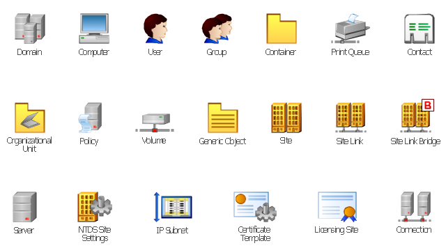
The vector stencils library "Active Directory" contains 20 symbols of Active Directory objects for drawing AD network diagrams. It helps network and system administrators to visualize Microsoft Windows Active Directory structures for network design, installation and maintainance.
"Objects.
An Active Directory structure is an arrangement of information about objects. The objects fall into two broad categories: resources (e.g., printers) and security principals (user or computer accounts and groups). Security principals are assigned unique security identifiers (SIDs).
Each object represents a single entity - whether a user, a computer, a printer, or a group - and its attributes. Certain objects can contain other objects. An object is uniquely identified by its name and has a set of attributes - the characteristics and information that the object represents - defined by a schema, which also determines the kinds of objects that can be stored in Active Directory.
The schema object lets administrators extend or modify the schema when necessary. However, because each schema object is integral to the definition of Active Directory objects, deactivating or changing these objects can fundamentally change or disrupt a deployment. Schema changes automatically propagate throughout the system. Once created, an object can only be deactivated - not deleted. Changing the schema usually requires planning. Sites are implemented as a set of well-connected subnets." [Active Directory. Wikipedia]
The shapes example "Design elements - Active Directory" was created using the ConceptDraw PRO diagramming and vector drawing software extended with the Active Directory Diagrams solution from the Computer and Networks area of ConceptDraw Solution Park.
Active Directory symbols
The vector stencils library "Cisco network topology" contains 89 symbols of Cisco network devices and design elements for drawing computer network topology diagrams.
"There are two basic categories of network topologies:
(1) Physical topologies,
(2) Logical topologies.
The shape of the cabling layout used to link devices is called the physical topology of the network. This refers to the layout of cabling, the locations of nodes, and the interconnections between the nodes and the cabling. The physical topology of a network is determined by the capabilities of the network access devices and media, the level of control or fault tolerance desired, and the cost associated with cabling or telecommunications circuits.
The logical topology in contrast, is the way that the signals act on the network media, or the way that the data passes through the network from one device to the next without regard to the physical interconnection of the devices." [Network topology. Wikipedia]
The symbols example "Cisco network topology - Vector stencils library" was created using the ConceptDraw PRO diagramming and vector drawing software extended with the Cisco Network Diagrams solution from the Computer and Networks area of ConceptDraw Solution Park.
www.conceptdraw.com/ solution-park/ computer-networks-cisco
Router

Broadband router

Router firewall

Wireless router

Workgroup switch

ATM switch

ISDN switch

Multilayer switch

Protocol translator

Communications server

Transpath

Bridge

Terminal server

Route switch processor

Content engine (cache director)
-cisco-network-topology---vector-stencils-library.png--diagram-flowchart-example.png)
Management engine (ME 1100)
-cisco-network-topology---vector-stencils-library.png--diagram-flowchart-example.png)
Switch processor

ITP

Voice gateway

BBSM

ATA

SIP Proxy server

NetRanger

Cisco 1000

IP

System controller

ACE

Directory server

ADM

Cisco Unity Express

Unity server

Cisco security

CallManager

DSLAM

H.323

CDM (Content Distribution Manager)
-cisco-network-topology---vector-stencils-library.png--diagram-flowchart-example.png)
ICM

Access point

Wireless bridge

Wireless connectivity

Guard

Mobile access router

Carrier Routing System (CRS)
-cisco-network-topology---vector-stencils-library.png--diagram-flowchart-example.png)
Vault

Workstation

PC

Macintosh

Cloud, gold

Cloud, white

Cloud, standard color

Cisco security management

PBX

DPT

Government building

Headquarters, blue

Router in building

Man

Woman

Workgroup switch, subdued

Router, subdued

File server

Firewall, horizontal

Firewall, vertical

Firewall, vertical, subdued

Lock

Key

Lock and key

Car

Truck

File cabinet

Breakout box

Breakout box, blue

Host

Relational database

Modem

BBS (Bulletin Board System)
-cisco-network-topology---vector-stencils-library.png--diagram-flowchart-example.png)
Satellite

Satellite dish

UPS

RPS

MAU

PAD

PAD X.28

Diskette

Contact center

Page icon
Antenna

Antenna, blue

Radio tower

- Bridge Router Icon
- Computer Network Bridge Icon
- Cisco Network Design. Cisco icons , shapes, stencils, symbols and ...
- Cisco Network Topology. Cisco icons , shapes, stencils and symbols ...
- Bridge Network Device Icon
- Wireless access point - Network diagram | Cisco - Vector stencils ...
- Cisco Routers. Cisco icons , shapes, stencils and symbols | Cisco ...
- Cisco Routers. Cisco icons , shapes, stencils and symbols | Network ...
- Design elements - Network layout floorplan | How To Create ...
- Design elements - Network layout floorplan | Design elements ...
- Cisco Network Design. Cisco icons , shapes, stencils, symbols and ...
- Network Icon | Local area network (LAN). Computer and Network ...
- Draw A Bridge Networking
- Network Security | Network Security Devices | Internet symbols ...
- Network Layout Floor Plans | Design elements - Network layout ...
- Network Layout Floor Plans | Design elements - Network layout ...
- Design elements - Network layout floorplan | How To Create ...
- Cisco Network Topology. Cisco icons , shapes, stencils and symbols ...
- Draw The Circuit Symbol Bridge Traic
- Cisco Telepresence. Cisco icons , shapes, stencils and symbols ...