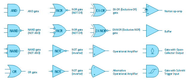
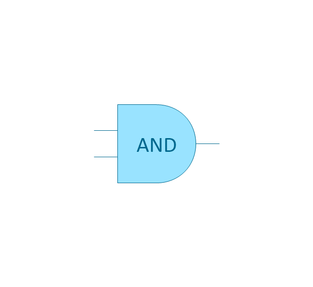
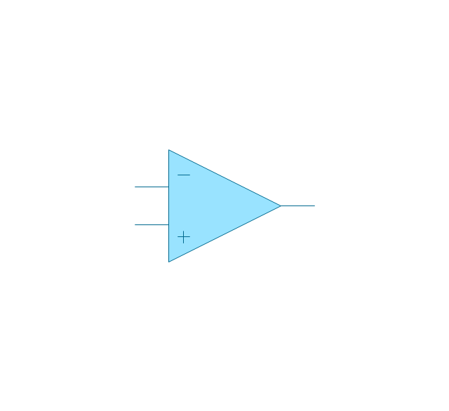
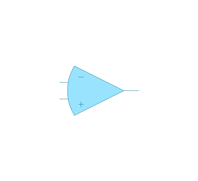
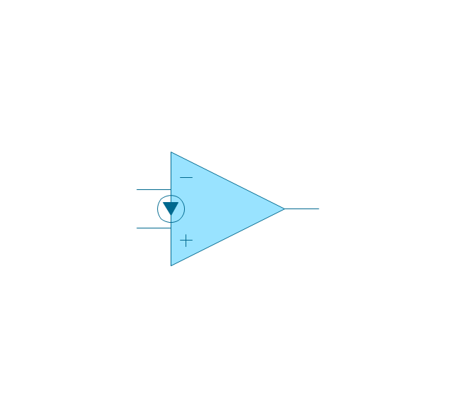
The vector stencils library "Logic gate diagram" contains 17 logical element symbols.
Use these shapes for drawing the logic gate diagrams in the ConceptDraw PRO diagramming and vector drawing software extended with the Electrical Engineering solution from the Engineering area of ConceptDraw Solution Park.
www.conceptdraw.com/ solution-park/ engineering-electrical
Use these shapes for drawing the logic gate diagrams in the ConceptDraw PRO diagramming and vector drawing software extended with the Electrical Engineering solution from the Engineering area of ConceptDraw Solution Park.
www.conceptdraw.com/ solution-park/ engineering-electrical
Electrical Symbols — Logic Gate Diagram
In electronics, a logic gate is an idealized or physical device implementing a Boolean function; that is, it performs a logical operation on one or more logical inputs, and produces a single logical output. Depending on the context, the term may refer to an ideal logic gate, one that has for instance zero rise time and unlimited fan-out, or it may refer to a non-ideal physical device 26 libraries of the Electrical Engineering Solution of ConceptDraw DIAGRAM make your electrical diagramming simple, efficient, and effective. You can simply and quickly drop the ready-to-use objects from libraries into your document to create the electrical diagram.The vector stencils library "Logic gate diagram" contains 17 logical element symbols.
Use these shapes for drawing the logic gate diagrams in the ConceptDraw PRO diagramming and vector drawing software extended with the Electrical Engineering solution from the Engineering area of ConceptDraw Solution Park.
www.conceptdraw.com/ solution-park/ engineering-electrical
Use these shapes for drawing the logic gate diagrams in the ConceptDraw PRO diagramming and vector drawing software extended with the Electrical Engineering solution from the Engineering area of ConceptDraw Solution Park.
www.conceptdraw.com/ solution-park/ engineering-electrical
The vector stencils library "Logic gate diagram" contains 17 logical element symbols.
Use these shapes for drawing the logic gate diagrams in the ConceptDraw PRO diagramming and vector drawing software extended with the Electrical Engineering solution from the Engineering area of ConceptDraw Solution Park.
www.conceptdraw.com/ solution-park/ engineering-electrical
Use these shapes for drawing the logic gate diagrams in the ConceptDraw PRO diagramming and vector drawing software extended with the Electrical Engineering solution from the Engineering area of ConceptDraw Solution Park.
www.conceptdraw.com/ solution-park/ engineering-electrical
Logic Diagram
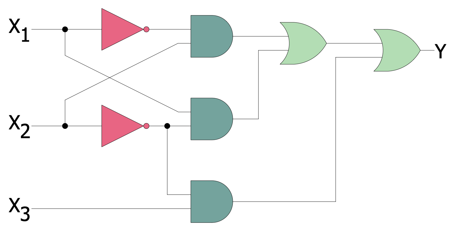
Logic diagrams are the main type of diagrams used to depict logical circuits. They show how the components and logic gates are connected in a digital circuit and allow predicting the expected output according to the included gates. Logic diagrams help receive precise results and avoid financial losses, time wastage, and getting unexpected results. ConceptDraw DIAGRAM software enhanced with Digital Electronics solution includes a collection of pre-made globally recognizable vector elements. They are useful for engineers, electronic designers, facility operators, and technical staff to create efficiently and faster Logic diagrams, Logic circuits, Digital electronic circuits, Computer logic diagrams, Process control logic diagrams.Logic Gate Symbols
The logical operations are fundamental for digital circuits and widely employed in integrated circuits. A logic gate is a basic element of a digital circuit and a device that performs logical functions. It is based on Boolean algebra. Digital Electronics solution for ConceptDraw DIAGRAM software includes a large collection of libraries with vector design elements of digital electrical symbols and logic gates of various standards, connections, electronic logic and flip flop symbols. It helps to easier and speed up the process of designing Logic diagrams for computer engineering, mechanical engineering, software development, network infrastructure, and building construction.Diagrams Mean Nothing
You are probably familiar with diagrams. But have you ever thought that they are useless? This article will explain you why.Venn Diagram
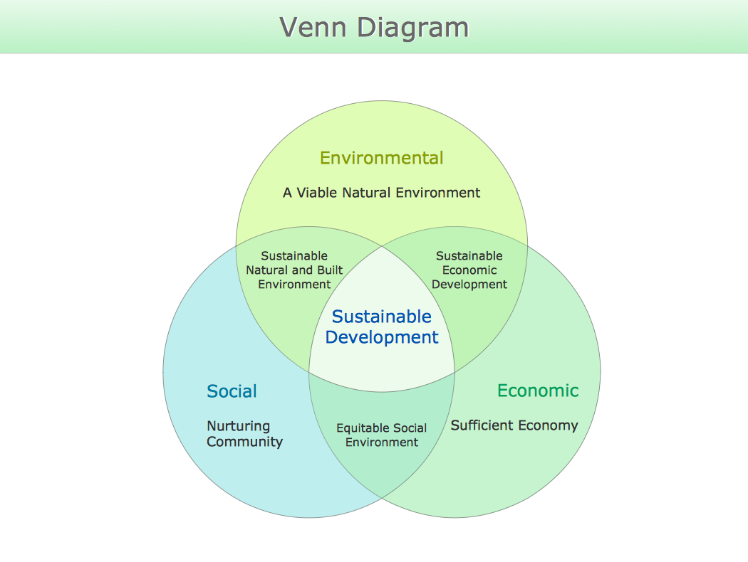
Venn diagrams are illustrations used in the branch of mathematics known as set theory. They show the mathematical or logical relationship between different groups of things (sets). A Venn diagram shows all the possible logical relations between the sets.Soccer (Football) Offside
It’s very convenient to explain the different tactics and positions using the visual drawings. ConceptDraw DIAGRAM software extended with the Soccer solution from the Sport area of ConceptDraw Solution Park provides libraries, templates and samples allowing specialists or soccer fans to draw the soccer-related diagrams and schemas of any complexity in a few minutes.Line Graph
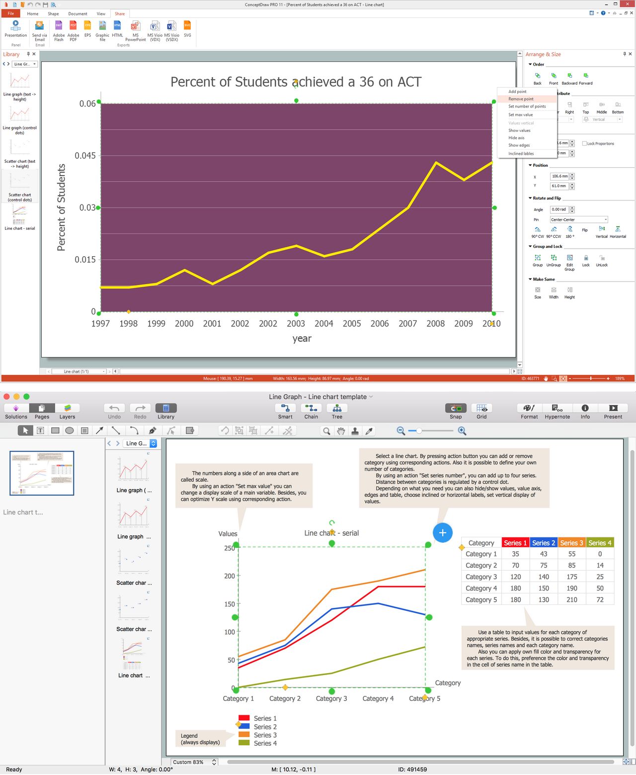
ConceptDraw DIAGRAM extended with Line Graphs solution from Graphs and Charts area of ConceptDraw Solution Park is ideal software for quick and simple drawing professional looking line graph.
 Digital Electronics
The Digital Electronics solution for ConceptDraw DIAGRAM includes a collection of multifarious diagrams samples and a large number of pre-made vector objects and digital electrical symbols of integrated circuit and connections, logic gate symbols of different kinds, electronic logic and flip flop symbols, etc. These symbols are perfect for logic diagram design, constructing schematics for digital electronics circuits and equipment, decoder, analog to digital converter, and more schematics. Use the solution tools at all stages of electrical engineering and digital electronics design.
The vector stencils library "Logic gate diagram" contains 17 element symbols for drawing the logic gate diagrams.
"To build a functionally complete logic system, relays, valves (vacuum tubes), or transistors can be used. The simplest family of logic gates using bipolar transistors is called resistor-transistor logic (RTL). Unlike simple diode logic gates (which do not have a gain element), RTL gates can be cascaded indefinitely to produce more complex logic functions. RTL gates were used in early integrated circuits. For higher speed and better density, the resistors used in RTL were replaced by diodes resulting in diode-transistor logic (DTL). Transistor-transistor logic (TTL) then supplanted DTL. As integrated circuits became more complex, bipolar transistors were replaced with smaller field-effect transistors (MOSFETs); see PMOS and NMOS. To reduce power consumption still further, most contemporary chip implementations of digital systems now use CMOS logic. CMOS uses complementary (both n-channel and p-channel) MOSFET devices to achieve a high speed with low power dissipation." [Logic gate. Wikipedia]
The symbols example "Design elements - Logic gate diagram" was drawn using the ConceptDraw PRO diagramming and vector drawing software extended with the Electrical Engineering solution from the Engineering area of ConceptDraw Solution Park.
 Divided Bar Diagrams
Divided Bar Diagrams Solution extends the capabilities of ConceptDraw DIAGRAM with templates, samples, and a library of vector stencils for drawing high impact and professional Divided Bar Diagrams and Graphs, Bar Diagram Math, and Stacked Graph. Divided Bar Diagram library objects include a legend that describes categories and can be shown or hidden, moved into a diagram; some objects also include a table of input values for categories. Enter your data in the table, and the segments will be displayed on the chart in accordance with the table data; when you make changes, the chart changes automatically.
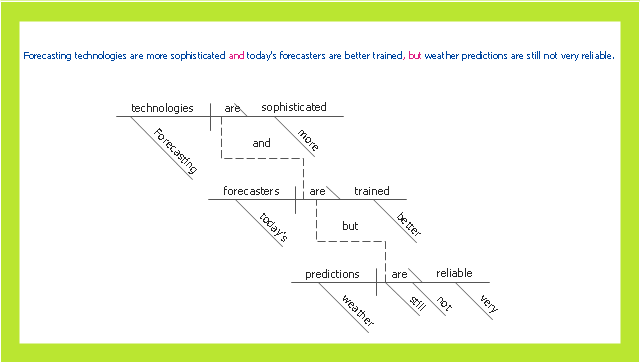
This sentence diagram sample was createb on the base of the webpage "Diagramming Sentences" from the website of the Capital Community College, Hartford CT. [grammar.ccc.commnet.edu/ grammar/ diagrams2/ one_ pager2.htm]
"In grammar, clause structure refers to the classification of sentences based on the number and kind of clauses in their syntactic structure. Such division is an element of traditional grammar.
A simple sentence consists of only one clause. A compound sentence consists of two or more independent clauses. A complex sentence has at least one independent clause plus at least one dependent clause.
A sentence consisting of one or more dependent clauses plus two or more independent clauses may be called a complex-compound sentence or compound-complex sentence. ...
A compound sentence is composed of at least two independent clauses. It does not require a dependent clause. The clauses are joined by a coordinating conjunction (with or without a comma), a semicolon that functions as a conjunction, a colon instead of a semicolon between two sentences when the second sentence explains or illustrates the first sentence and no coordinating conjunction is being used to connect the sentences, or a conjunctive adverb preceded by a semicolon. A conjunction can be used to make a compound sentence. Conjunctions are words such as for, and, nor, but, or, yet, so (the first letters of which spell "fanboys"). The use of a comma to separate two independent clauses without the addition of an appropriate conjunction is called a comma splice and is generally considered an error (when used in the English language)." [Sentence clause structure. Wikipedia]
The example "Compound sentence" was created using the ConceptDraw PRO diagramming and vector drawing software extended with the Language Learning solution from the Science and Education area of ConceptDraw Solution Park.
Electrical Diagram Symbols F.A.Q.How to Use Electrical ConceptDraw Diagram Software
When drawing Electrical Schematics, Electrical Circuit Diagrams, Power Systems Diagrams, Circuit and Wiring Diagrams, Digital and Analog Logic Schemes, you will obligatory need the electrical symbols and pictograms to represent various electrical and electronic devices, such as resistors, wires, transistors, inductors, batteries, switches, lamps, readouts, amplifiers, repeaters, relays, transmission paths, semiconductors, generators, and many more. Today these symbols are internationally standardized, so the diagrams designed using them are recognizable and comprehensible by specialists from different countries.
Electrical Engineering Solution included to ConceptDraw Solution Park provides 26 libraries with 926 commonly used electrical schematic and electrical engineering symbols making the reality the easy drawing of Electrical diagrams, schematics and blueprints. Now you need only a few minutes to create great-looking Electrical diagram, simply choose required electrical design elements from the libraries, drag them on the needed places at the document and connect in a suitable way.
Spatial infographics Design Elements: Location Map
Infographic Design Elements for visually present various geographically distributed information.Developing Entity Relationship Diagrams
When you need to visually represent the structure of relational database, Entity relationship diagram (ERD) is a type of diagram for that case. Most entity-relationship diagrams can be built with objects from Flowchart solution or ERD Solution which contains inbuilt templates. Follow these steps to create your own custom ERD diagram. Don't be frightened if it looks complex, ConceptDraw DIAGRAM makes it easy to create an ERD, and hundreds of other diagrams, in minutes.Circuits and Logic Diagram Software
Circuit diagram is a graphical representation of electrical circuits, wire connections between devices, among them power and signal connections. Circuit diagrams are successfully used during design, construction and maintenance of different electrical and electronic equipment, and also for visualizing expressions using a boolean algebra in the computer science. These diagrams don't show a physical arrangement of components. One of advanced application of ConceptDraw DIAGRAM software is electrical engineering. Included to ConceptDraw Solution Park, Electrical Engineering solution from the Engineering area offers templates, samples and incredibly large quantity of vector design elements of circuits and logic symbols, which are helpful for professional drawing Circuit diagrams, Logic circuit diagrams, Wiring diagrams, Electrical schematics, Digital and Analog logic designs, Integrated circuit schematics, Circuit board and Amplifier diagrams, Power systems diagrams, Maintenance and Repair diagrams of any difficulty.DFD Library System
The Data Flow Diagram (DFD) is a graphical technique used for effective modeling and analyzing the information processes and systems. Having at the disposal the DFD library system and newest powerful tools of ConceptDraw DIAGRAM diagramming and vector drawing software supplied with Data Flow Diagrams (DFD) solution from the Software Development area of ConceptDraw Solution Park, you can design fast and easy the Data flow diagrams, Data flowcharts, Data flow models, Data flow process diagrams, Process-oriented models, Data-oriented models, Data process diagrams, Structured analysis diagrams, Information flow diagrams of any type and complexity. For designing the Data Flow Diagrams in ConceptDraw DIAGRAM software are used the simple DFD flowchart symbols from the offered DFD libraries - Data Flow Diagram (DFD) library, Yourdon and Coad Notation library, and Gane-Sarson Notation library. The DFD objects are need to be connected each other by the arrows to depict the data flow from one step to another, that you can do in seconds in ConceptDraw DIAGRAM , as well as set desired design of your diagram.- Logic gate diagram - Vector stencils library
- Vector stencils library | Electrical Symbols — Logic Gate Diagram
- Design elements - Logic gate diagram | Example Of Nor Gate
- Logic gate diagram - Vector stencils library | Nor Schmitt Trigger
- Logic gate diagram - Vector stencils library | Symbol Ex Nor Gate
- Electrical Symbols — Logic Gate Diagram | Electrical Symbols ...
- Logic gate diagram - Vector stencils library
- Logic gate diagram - Vector stencils library
- Logic gate diagram - Vector stencils library
- Logic gate diagram - Vector stencils library | The Not Gate

-logic-gate-diagram---vector-stencils-library.png--diagram-flowchart-example.png)
-logic-gate-diagram---vector-stencils-library.png--diagram-flowchart-example.png)
-logic-gate-diagram---vector-stencils-library.png--diagram-flowchart-example.png)
-gate-logic-gate-diagram---vector-stencils-library.png--diagram-flowchart-example.png)
-gate-logic-gate-diagram---vector-stencils-library.png--diagram-flowchart-example.png)

-logic-gate-diagram---vector-stencils-library.png--diagram-flowchart-example.png)
-logic-gate-diagram---vector-stencils-library.png--diagram-flowchart-example.png)
-logic-gate-diagram---vector-stencils-library.png--diagram-flowchart-example.png)




.png)

