Program Evaluation and Review Technique (PERT) with ConceptDraw DIAGRAM

Basic Flowchart Symbols and Meaning


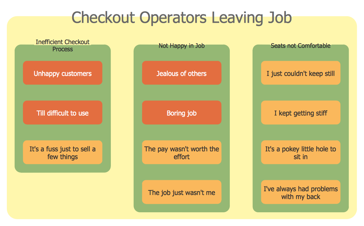
Affinity Diagram
ERD Symbols and Meanings


Data Flow Diagram

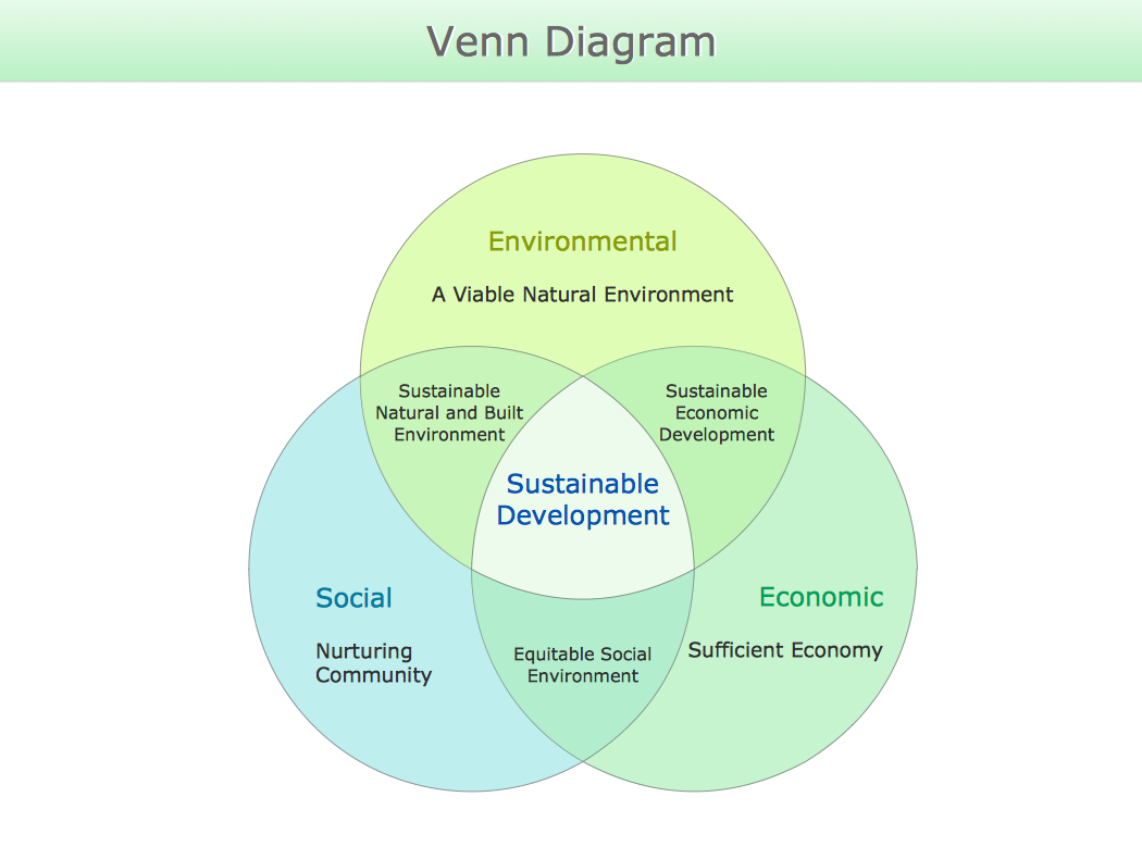
Venn Diagram
Successful Strategic Plan
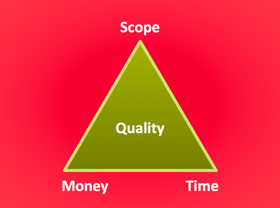
Pyramid Diagram
HelpDesk
How to Create a Timeline Diagram

- How to Plan and Allocate Resources in Your Project on Mac | Gant ...
- Gantt Chart Mac Numbers
- PM Dashboards | How to Create Project Dashboard on Mac | Project ...
- Free Gantt Chart Template For Mac Numbers
- Project Timeline | Timeline Examples | How to Make a Timeline ...
- Conceptdraw.com: Mind Map Software, Drawing Tools | Project ...
- Gant Chart in Project Management | What Constitutes a Project ...
- Gantt Diagramm Numbers
- Status Dashboard | Project management task status dashboard ...