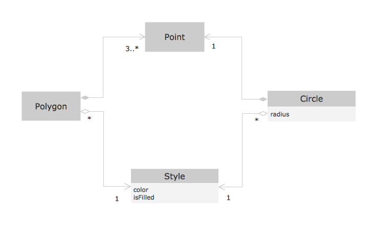
Yourdon and Coad Diagram

OOSE Method
 Data Flow Diagrams (DFD)
Data Flow Diagrams solution extends ConceptDraw DIAGRAM software with templates, samples and libraries of vector stencils for drawing the data flow diagrams (DFD).
Data Flow Diagram

Data Flow Diagram Examples

Structured Systems Analysis and Design Method. SSADM with ConceptDraw DIAGRAM

Data Flow Diagram Example

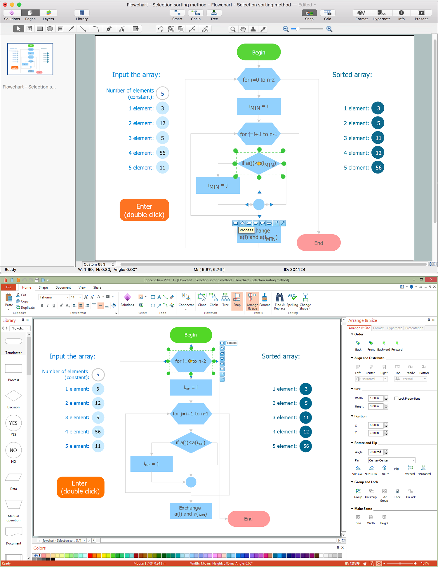
Diagram Flow Chart
Context Diagram Template

This template shows the Context Diagram. It was created in ConceptDraw DIAGRAM diagramming and vector drawing software using the Block Diagrams Solution from the “Diagrams” area of ConceptDraw Solution Park. The context diagram graphically identifies the system. external factors, and relations between them. It’s a high level view of the system. The context diagrams are widely used in software engineering and systems engineering for designing the systems that process the information.
Example of DFD for Online Store (Data Flow Diagram)


- Object Model Coad Methodology
- Coad /Yourdon's Object -Oriented Analysis model | Cross-Functional ...
- Derivation Of Object Model Coad Methodology
- Yourdon and Coad Diagram | OOSE Method | Coad /Yourdon's ...
- Coad /Yourdon's Object -Oriented Analysis model | Software ...
- Booch OOD Diagram | Examples for OOSE Method | Object -Oriented ...
- Object -Oriented Design | Booch OOD Diagram | Coad /Yourdon's ...
- Booch OOD Diagram | Object -Oriented Development (OOD) Method ...
- Methodology For Object Oriented Design Booch And Chen And Chen
- DFD, Yourdon and Coad notation - Template