HelpDesk
How to Create a Bank ATM Use Case Diagram
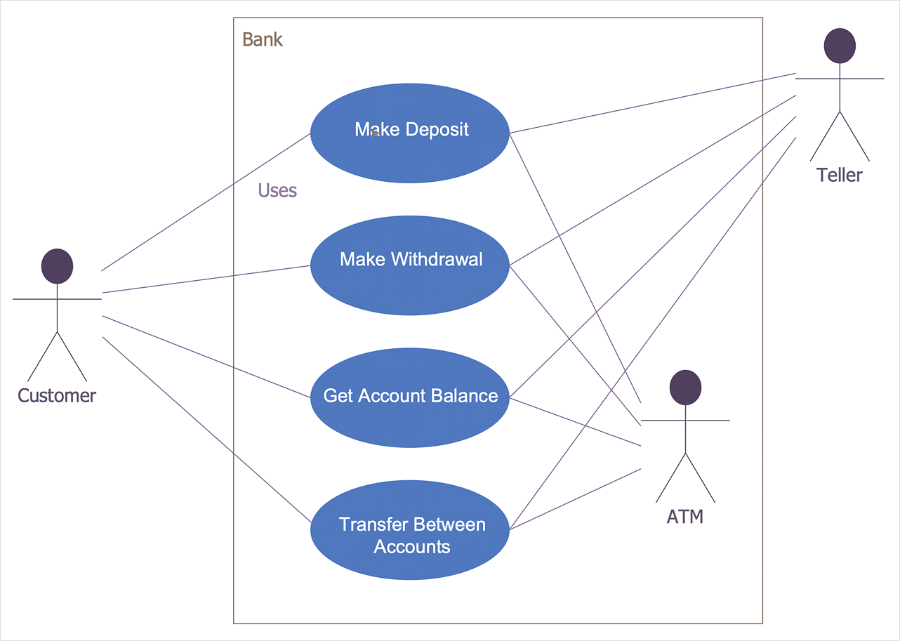
UML diagrams are often used in banking management for documenting a banking system. In particular, the interaction of bank customers with an automated teller machine (ATM) can be represented in a Use Case diagram. Before the software code for an ATM, or any other system design, is written, it is necessary to create a visual representation of any object-oriented processes. This is done most effectively by creating a Unified Modeling Language (UML) diagram, using object-oriented modeling. UML works as a general purpose modeling language for software engineers or system analysts, offering a number of different diagram styles with which to visually depict all aspects of a software system. ConceptDraw DIAGRAM diagramming software, enhanced and expanded with the ATM UML Diagrams solution, offers the full range of icons, templates and design elements needed to faithfully represent ATM and banking information system architecture using UML standards. The ATM UML Diagrams solution is useful for beginner and advanced users alike. More experienced users will appreciate a full range of vector stencil libraries and ConceptDraw DIAGRAM 's powerful software, that allows you to create your ATM UML diagram in a matter of moments.Software development with ConceptDraw DIAGRAM
Modern software development requires creation of large amount of graphic documentation, these are the diagrams describing the work of applications in various notations and cuts, also GUI design and documentation on project management. ConceptDraw DIAGRAM technical and business graphics application possesses powerful tools for software development and designing technical documentation for object-oriented projects. Solutions included to the Software Development area of ConceptDraw Solution Park provide the specialists with possibility easily and quickly create graphic documentation. They deliver effective help in drawing thanks to the included package of templates, samples, examples, and libraries with numerous ready-to-use vector objects that allow easily design class hierarchies, object hierarchies, visual object-oriented designs, flowcharts, GUI designs, database designs, visualize the data with use of the most popular notations, including the UML and Booch notations, easy manage the development projects, automate projection and development.- Coad/Yourdon's Object - Oriented Analysis model | Data Flow ...
- Coad/Yourdon's Object - Oriented Analysis model | Data Flow ...
- Data Flow Diagram Symbols. DFD Library | Coad/Yourdon's Object ...
- Coad/Yourdon's Object - Oriented Analysis model | Booch OOD ...
- Yourdon and Coad Diagram | Coad/Yourdon's Object - Oriented ...
- Coad/Yourdon's Object - Oriented Analysis model | Coad/Yourdon's ...
- Object - Oriented Design | Booch OOD Diagram | Coad/Yourdon's ...
- Coad/Yourdon's Object - Oriented Analysis model | Yourdon and ...
- Yourdon and Coad Diagram | Coad/Yourdon's Object - Oriented ...
- Yourdon and Coad Diagram | Coad/Yourdon's Object - Oriented ...
- Coad/Yourdon's Object - Oriented Analysis model | Yourdon and ...
- Process Flowchart | Data Flow Diagram Symbols. DFD Library ...
- Database Design | Database Flowchart Symbols | Data Flow ...
- Yourdon and Coad Diagram | Design Data Flow . DFD Library | DFD ...
- Structured Systems Analysis and Design Method (SSADM) with ...
- Coad/Yourdon's Object - Oriented Analysis model | Coadsys
- Basic Flowchart Symbols and Meaning | Database Flowchart ...
- Structured Systems Analysis and Design Method (SSADM) with ...
- Data Flow Diagram In Student Result Analysis System
- Object - Oriented Development (OOD) Method | Booch OOD Diagram ...

