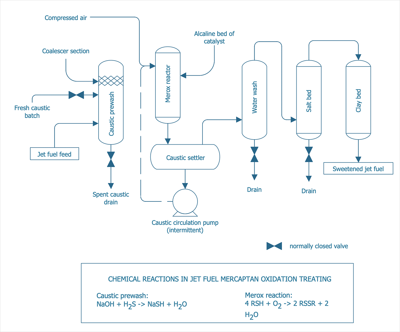
Process Flow Diagram Symbols
Chemical and Process Engineering Solution from the Industrial Engineering Area of ConceptDraw Solution Park is a unique tool which contains variety of predesigned process flow diagram symbols for easy creating various Chemical and Process Flow Diagrams in ConceptDraw DIAGRAM.
 Chemical and Process Engineering
This chemical engineering solution extends ConceptDraw DIAGRAM.9.5 (or later) with process flow diagram symbols, samples, process diagrams templates and libraries of design elements for creating process and instrumentation diagrams, block flow diagrams (BFD
Process Engineering
ConceptDraw DIAGRAM diagramming and vector drawing software supplied with Chemical and Process Engineering Solution from the Industrial Engineering Area of ConceptDraw Solution Park is powerful and effective process engineering software.HelpDesk
How to Draw a Chemical Process Flow Diagram
Process Flow Diagram widely used in modeling of processes in the chemical industry. A Chemical Process Flow diagram (PFD) is a specialized type of flowchart. With the help of Chemical Process Flow Diagram engineers can easily specify the general scheme of the processes and chemical plant equipment. Chemical Process Flow Diagram displays the real scheme of the chemical process, the relationship between the equipment and the technical characteristics of the process. Chemical Process Flow Diagram illustrates the connections between the basic equipment as well as the overall structure of pipelines and other supporting equipment. The purpose of the PFD is to build the image of the basic idea of the chemical process. ConceptDraw DIAGRAM together with its Chemical and Process Engineering solution delivers the possibility to design Chemical Process Flow diagrams. It is designed for chemical industry engineers and designers.Building Drawing. Design Element: Piping Plan
When you are going to build a house or to make repairs of new built home, apartment, office, shop, or to renovate any other premises, in many cases you will need to make the package of drawings, plans and documents, including the such important plans as the Overall floor plan, Interior design plan, Ceiling plan, Electrical system plan, and of course the Plumbing plan, Water supply system plan, and Piping Plan. When choosing between the modern software for building construction, planning and design, we recommend you to select the multifunctional building plan software ConceptDraw DIAGRAM enhanced with Plumbing and Piping Plans solution from the Building Plans area of ConceptDraw Solution Park. This solution provides large variety of examples, samples, quick-start templates and libraries of pipes, plumbing and valves vector design elements for design and construction the Plumbing and Piping Plans, schematics and annotated diagrams for hot and cold water supply systems, water lines and waste water disposal systems.
- Process Flowchart | Process Flow Diagram Symbols | Process flow ...
- Crude oil distillation unit - PFD | Natural gas condensate - PFD ...
- Oil And Gas Production Diagram
- Oil And Gas Production Process Flow Diagram
- Visio Template Heating Pipeline
- Schematic Diagram Of Oil And Gas Refinery
- Use Of Flow Sheet In Petroleum Production Processes
- Oil And Gas Production Methods Flow Chart
- Process Flowchart | Process Flow Diagram Symbols | How to Draw a ...
- Sample Oil And Gas Process Flow Diagram In Pdf
- Process Flow Diagram Symbols | Process Flowchart | Chemical and ...
- Process Flowchart | Types of Flowcharts | How to Draw a Chemical ...
- Process flow diagram - Typical oil refinery | Process Flowchart ...
- Processes And Flow Chart In Crude Oil Production
- Process Flowchart | Basic Flowchart Symbols and Meaning ...
- Process flow diagram - Typical oil refinery | Types of Flowcharts ...
- Process flow diagram - Typical oil refinery | Chemical and Process ...
- Process flow diagram - Typical oil refinery
- Onion Diagram Process Design | Amine treating unit schematic ...
- Amine treating unit schematic diagram | Natural gas condensate ...


