 SYSML
SYSML
The SysML solution helps to present diagrams using Systems Modeling Language; a perfect tool for system engineering.
"RT-middleware (Robotics Technology Middleware) is a common platform standards for Robots based on the distributed object technology. RT-middleware supports the construction of various networked robotic systems by the integration of various network enabled robotic elements called RT-Components. The specification standard of the RT-component is discussed / defined by the Object Management Group (OMG). ...
In the RT-middleware, robotics elements, such as actuators, are regarded as RT-components, and the whole robotic system is constructed by connecting those RT-components. This distributed architecture helps developers to re-use the robotic elements, and boosts the reliability of the robotic system.
Each RT-component has port as an endpoint for communicating other RT-components. Every port has its type and the ports which have the same type can be connected each other.
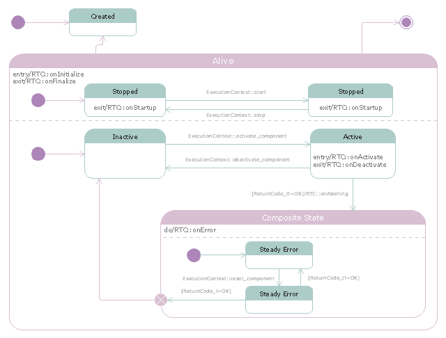
RT-components also has its state, so the RT-components behaves as state machines. The states that RT-components can have are CREATED, INACTIVE, ACTIVE, and ERROR, and the states and behaviors are controlled by the execution-context. If developers want to change the behavior of their RT-components, the execution-context can be replaced at run-time." [RT middleware. Wikipedia]
The UML state machine diagram example "State transitions of RT-component" was created using the ConceptDraw PRO diagramming and vector drawing software extended with the Rapid UML solution from the Software Development area of ConceptDraw Solution Park.
- State Diagram Example - Online Store | State Machine Diagram ...
- State Diagram Example - Online Store | UML Component Diagram ...
- State Diagrams For Online Ordering System
- State Diagram For Online Ordering System
- State Chart Diagrams For Online Order
- Deployment Diagram For Online Ordering System
- State Diagram Example - Online Store | Design elements - UML ...
- Behavioral Uml Diagrams
- State Diagram Example - Online Store | State Machine Diagram ...
- UML Component Diagram Example - Online Shopping | State ...
- State Machine Diagram For Online Shopping System
- Purchase order processing UML activity diagram | Event-driven ...
- Diagramming Software for Design UML State Machine Diagrams ...
- UML Diagrams with ConceptDraw PRO | UML Diagram | Software ...
- | State Machine Diagram | How to Create a Bank ATM Use Case ...
- State Diagram Example - Online Store | UML Diagram | Design ...
- UML use case diagram - Banking system | UML Diagram | Process ...
- Design elements - Bank UML state machine diagram | UML Diagram ...
- State Diagram Example - Online Store | UML State Machine ...
- State Chart Diagram For Bank
