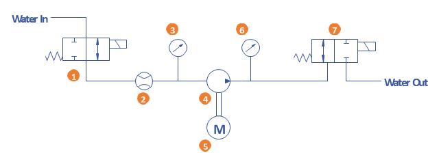
A simple hydraulic schematic showing apparatus for testing the strength of a hydraulic hose splice.
Water enters through normally closed solenoid valve (1) and passes through intake flow meter (2) to high pressure pump (4). Intake water pressure is monitored by pressure gauge (3). The hose to be tested connects between pump (4) and normally open solenoid activated drain valve (7). To test the hose, pump drive motor (5) is turned on, the solenoid of drain valve (7) is activated, closing the valve, and the pump is run to pressurize the hose. Test pressure is monitored by gauge (6). When the test is complete or the hose fails, the solenoid of drain valve (7) is deactivated, opening valve and discharging water, depressurizing the system. All components are operated electrically by a remote control circuit so that the operator may perform the test from a protected location, monitoring it with a camera and video monitor.
This hydraulic schematic example was redrawn using ConceptDraw PRO diagramming and vector drawing software from the Wikimedia Commons file: Hydraulic schematic.jpg.
[commons.wikimedia.org/ wiki/ File:Hydraulic_ schematic.jpg]
This file is licensed under the Creative Commons Attribution-Share Alike 3.0 Unported license.
[creativecommons.org/ licenses/ by-sa/ 3.0/ deed.en]
The hydraulic schematic example "Apparatus for testing the strength of a hydraulic hose splice" is included in the Mechanical Engineering solution from the Engineering area of ConceptDraw Solution Park.
- Entity Relationship Diagram Open Source
- Open Source Network Diagramming Tool
- Open Source Entity Relationship Diagram Tool
- Best Open Source Software Swim Lanes
- SysML Diagram | SysML | Process Flowchart | Open Source Uml ...
- Fault Tree Analysis Software Open Source
- Introduction to Cloud Computing Architecture | Sequence Diagram ...
- SysML | Data Flow Diagrams | Stakeholder Onion Diagrams ...
- Free Cad Open Source
- Open Source Uml Software
- Stakeholder Onion Diagrams | Office Layout Plans | Comparison ...
- Open Source Cabinet Design Software
- SysML Diagram | SysML | UML Diagrams with ConceptDraw PRO ...
- Er Diagram Open Source
- Open Source Agile Project Management
- Org Chart Software Open Source
- Building Drawing Design Element: Piping Plan | Plumbing and ...
- Open Source Workflow Management System
- Open Source Visio Alternatives
- Electrical Symbols, Electrical Diagram Symbols | Design elements ...
