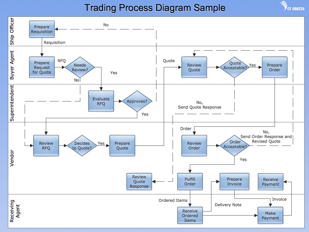
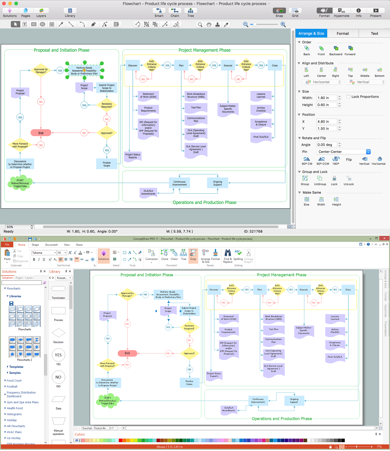
Vertical Cross Functional Flowchart
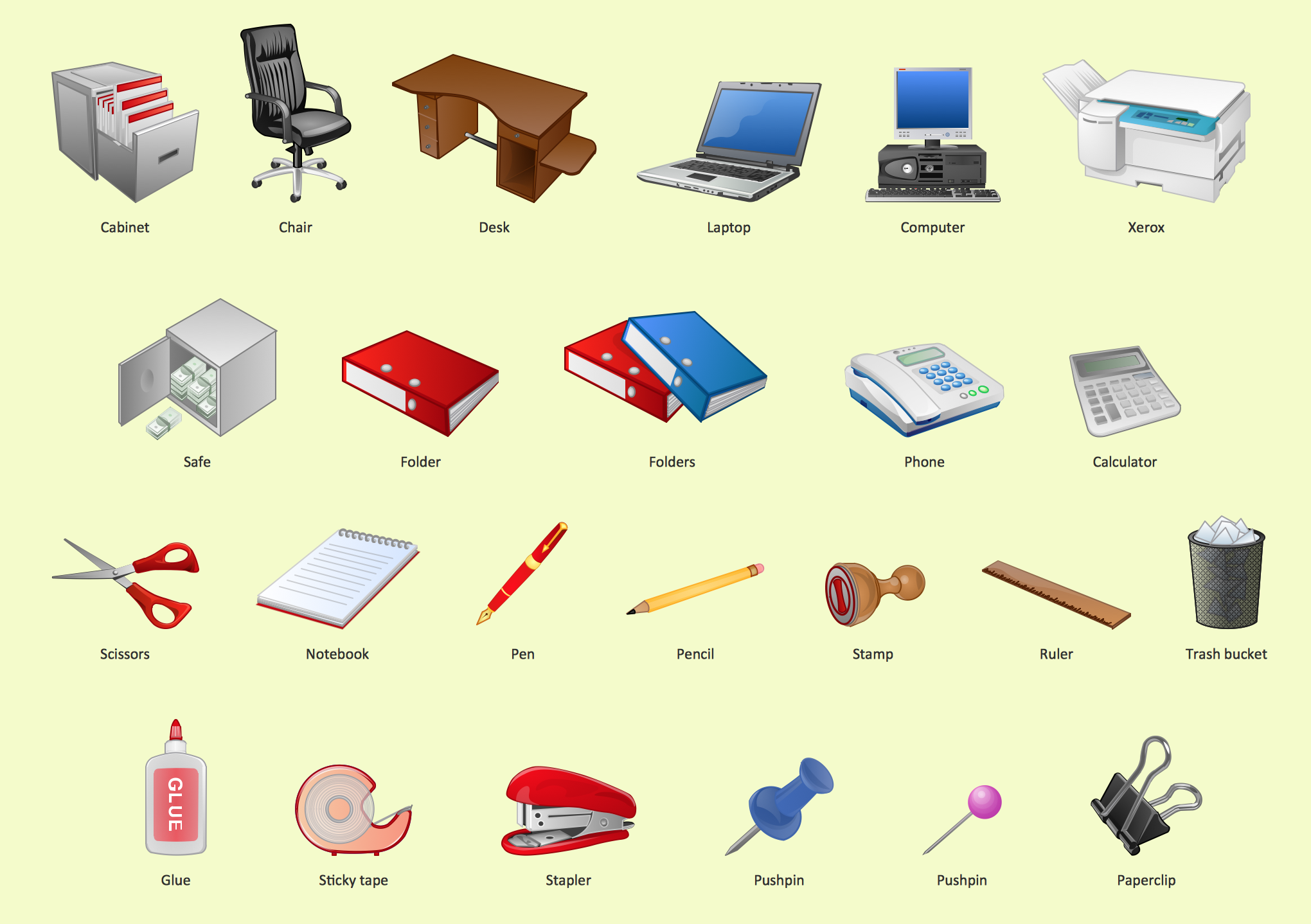
Office - Design Elements
The vector stencils libraries "Pipes 1" and "Pipes 2" contain 28 and 48 pipe, tubing and fitting symbols, respectively.
"A fitting is used in pipe plumbing systems to connect straight pipe or tubing sections, to adapt to different sizes or shapes, and for other purposes, such as regulating or measuring fluid flow. The term plumbing is generally used to describe conveyance of water, gas, or liquid waste in ordinary domestic or commercial environments, whereas piping is often used to describe high-performance (e.g. high pressure, high flow, high temperature, hazardous materials) conveyance of fluids in specialized applications. The term tubing is sometimes used for lighter-weight piping, especially types that are flexible enough to be supplied in coiled form.
Fittings (especially uncommon types) require money, time, materials, and tools to install, so they are a non-trivial part of piping and plumbing systems." [Piping and plumbing fitting. Wikipedia]
Use the design elements libraries "Pipes 1" and "Pipes 2" for drawing plumbing and piping building plans, schematic diagrams, blueprints, or technical drawings of waste water disposal systems, hot and cold water supply systems using the ConceptDraw PRO diagramming and vector drawing software.
The shapes libraries "Pipes 1" and "Pipes 2" are contained in the Plumbing and Piping Plans solution from the Building Plans area of ConceptDraw Solution Park.
Piping symbols
.png--diagram-flowchart-example.png)
Personal area (PAN) networks. Computer and Network Examples
 networks")

AWS Simple Icons for Architecture Diagrams

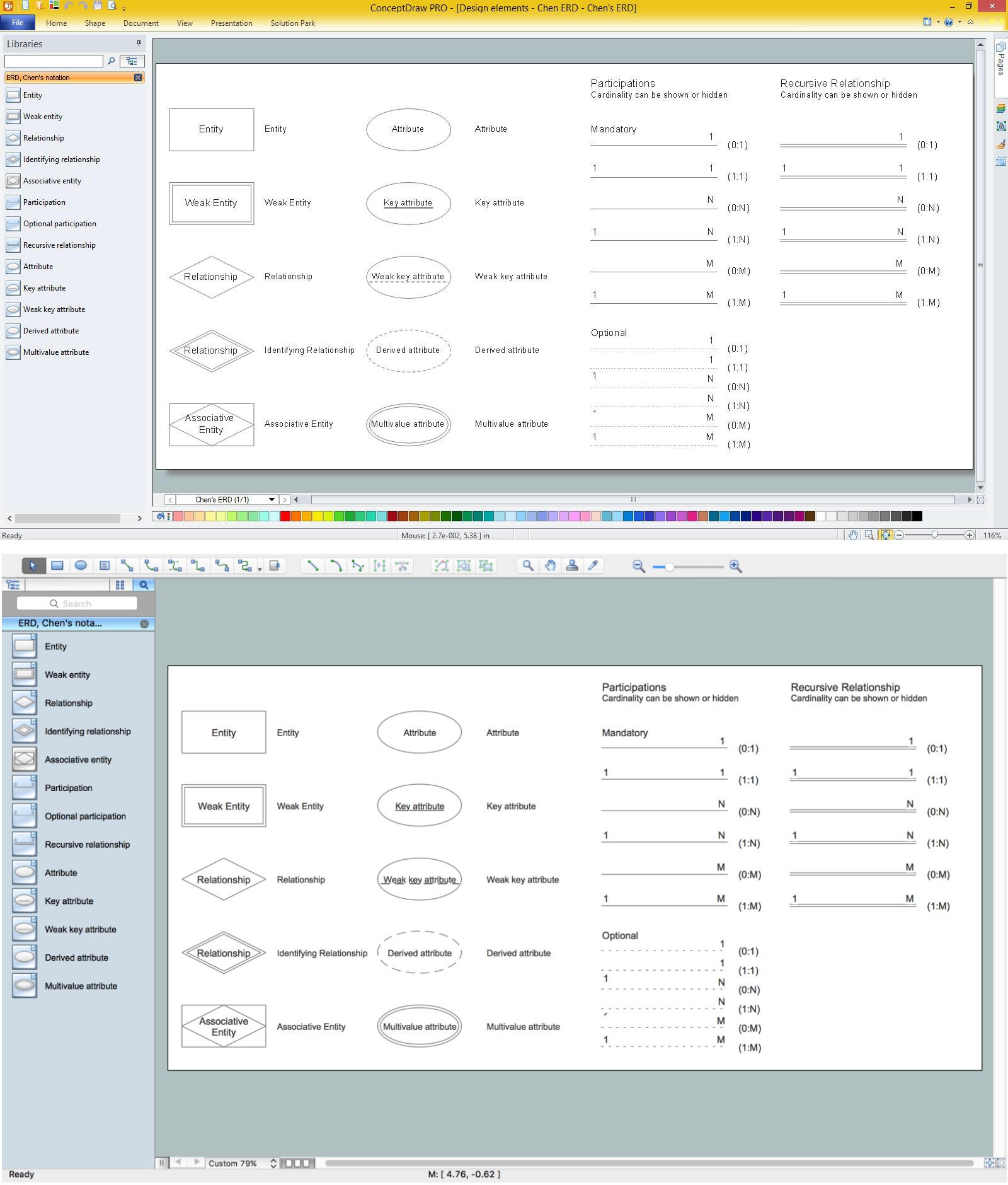
Entity Relationship Software

Design Element: Chen for Entity Relationship Diagram - ERD
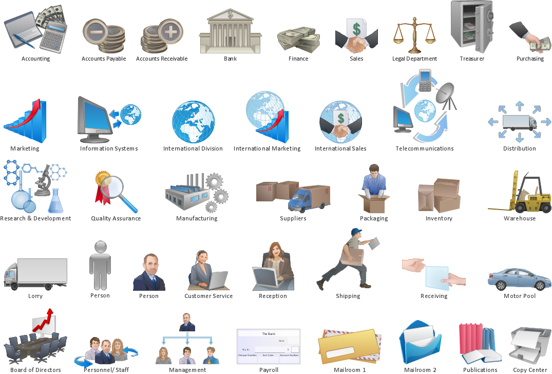
Business Processes

How to Design a Good Workflow
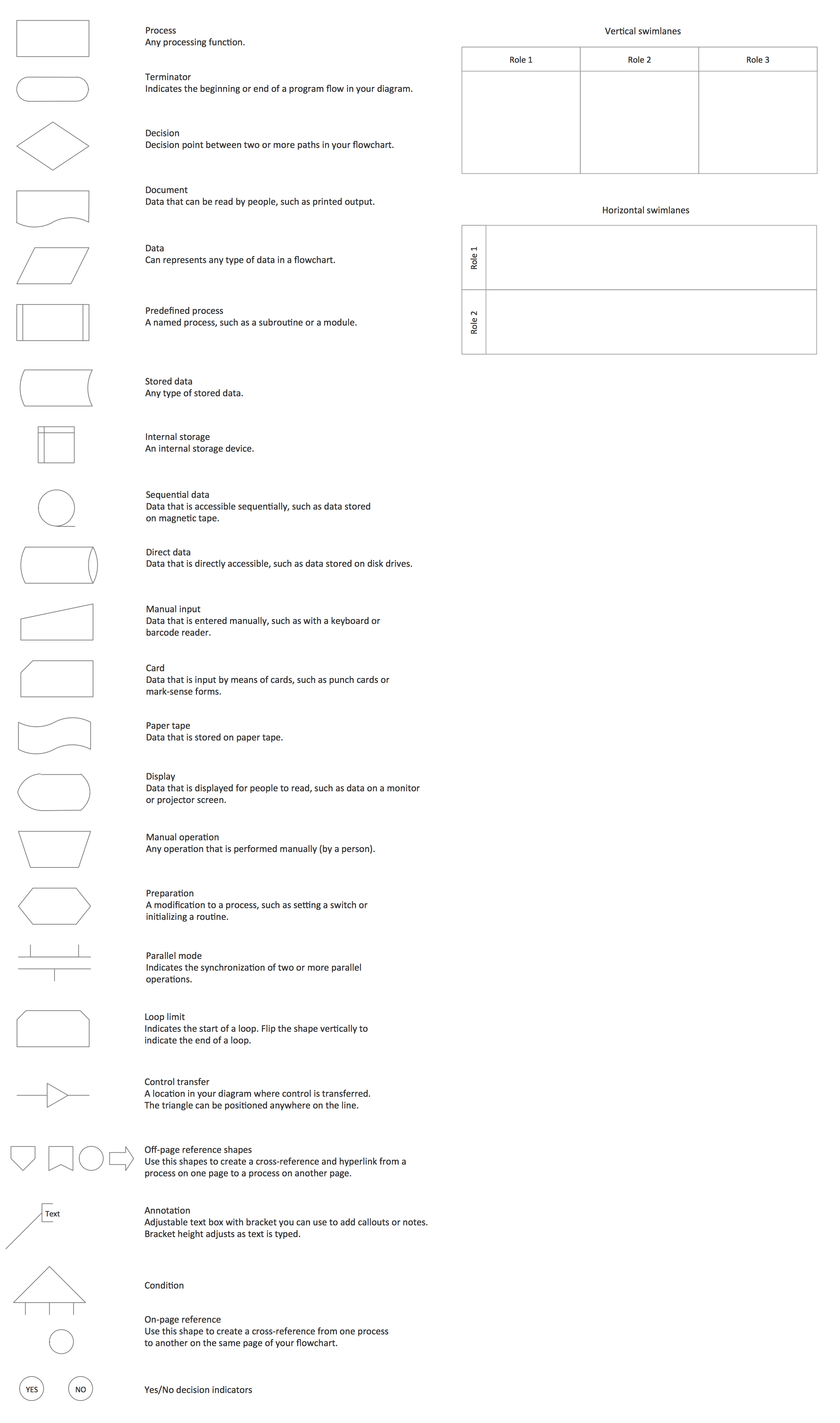
Cross Functional Flowchart Symbols
Draw Flowcharts with ConceptDraw
Business Process Mapping — How to Map a Work Process

Technical Flow Chart Example

- Mechanical Drawing Symbols | How To use House Electrical Plan ...
- Drawings Of Water Supply In Commercial Building
- Building Drawing Software for Designing Plumbing | Design ...
- Piping and Instrumentation Diagram Software | Building Drawing ...
- Interior Design Plumbing - Design Elements | Building Drawing ...
- Plumbing and Piping Plans | Design elements - Pipes (part 1 ...
- Construction Project Chart Examples | Process Flowchart | Building ...
- Building Drawing Software for Designing Plumbing | Interior Design ...
- Piping and Instrumentation Diagram Software | Building Drawing ...
- Piping and Instrumentation Diagram Software | Building Drawing ...
- Piping and Instrumentation Diagram Software | Building Drawing ...
- Building Drawing Software for Designing Plumbing | Building ...
- Building Drawing Software for Designing Plumbing | Interior Design ...
- How To use Furniture Symbols for Drawing Building Plan ...
- Plumbing and Piping Plans | Pipe Bender Plans | Building Drawing ...
- Building Drawing Design Element: Plumbing | Interior Design ...
- Plumbing and Piping Plans | Building Drawing Software for ...
- Building Drawing Design Element: Plumbing | Building Drawing ...
- Building Drawing Design Element: Piping Plan | Building Drawing ...
- Building Drawing Design Element: Plumbing | Interior Design ...