 Office Layout Plans
Office layouts and office plans are a special category of building plans and are often an obligatory requirement for precise and correct construction, design and exploitation office premises and business buildings. Designers and architects strive to make office plans and office floor plans simple and accurate, but at the same time unique, elegant, creative, and even extraordinary to easily increase the effectiveness of the work while attracting a large number of clients.
Basic Flowchart Symbols and Meaning


Entity Relationship Diagram Symbols

ERD Symbols and Meanings


Workflow Diagram Data
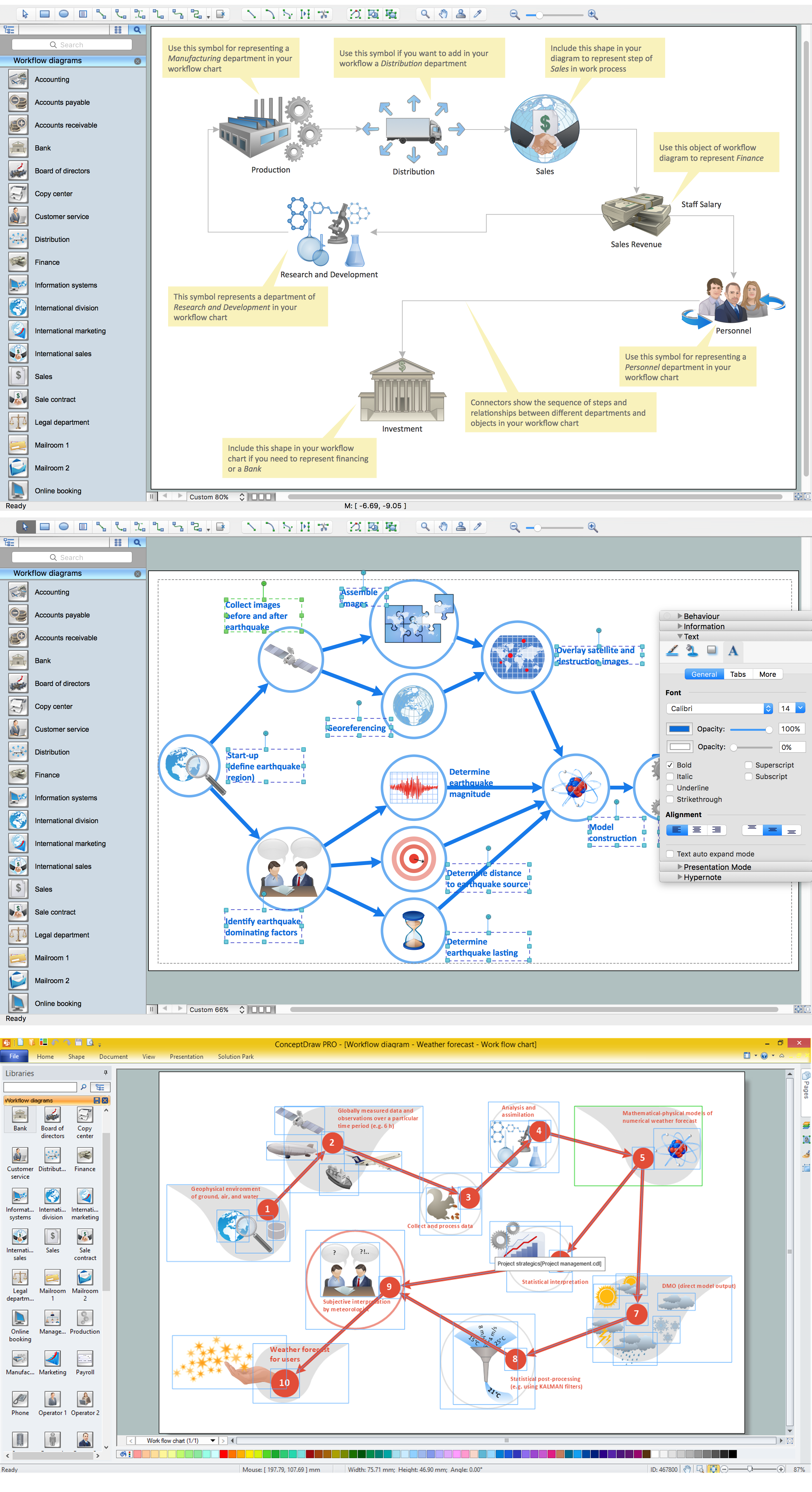
Business Process Flow Diagram

Flow Chart Symbols

Work Flow Process Chart

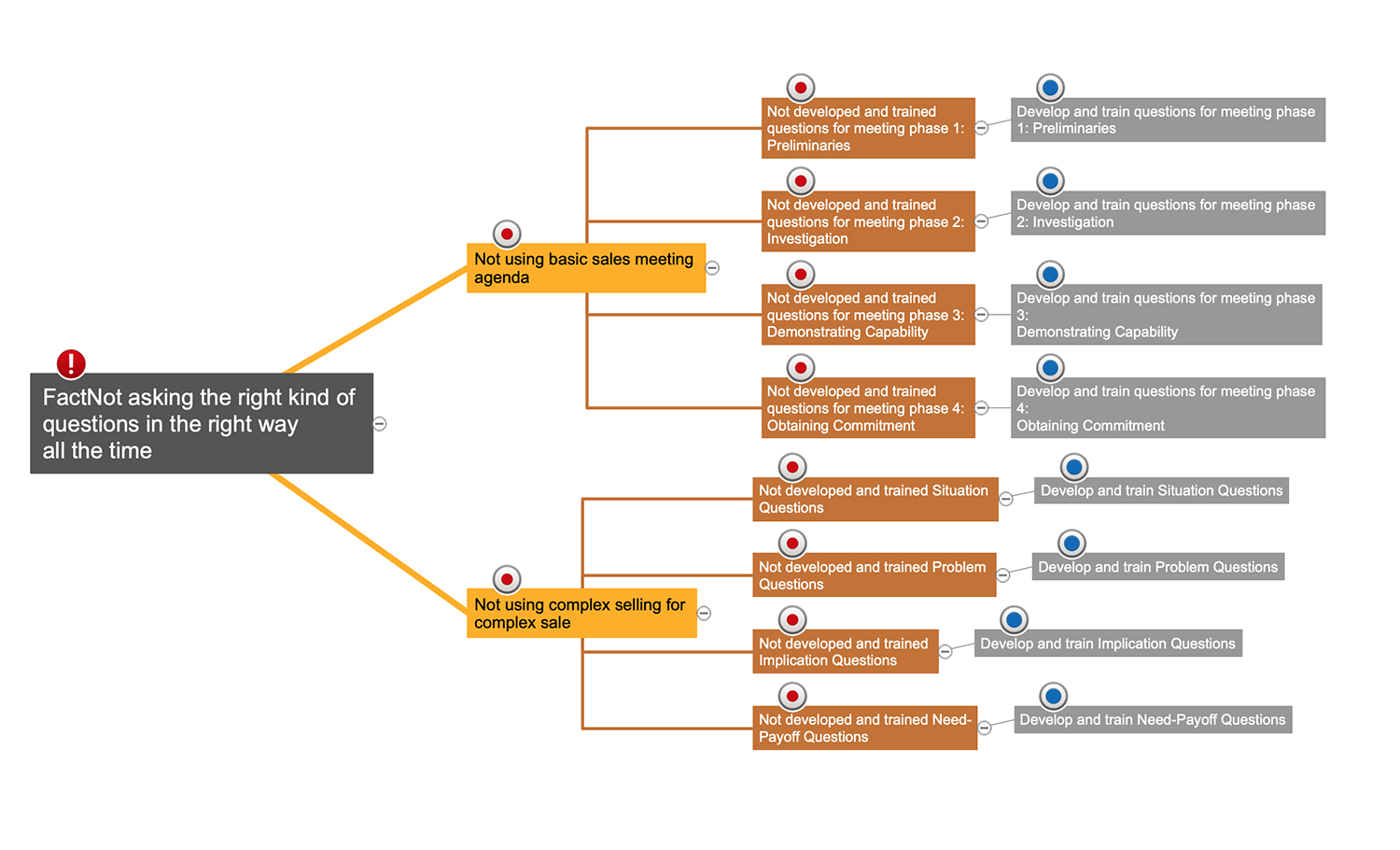
Cause and Effect Analysis

Data Flow Diagram Symbols. DFD Library

- Floor Plans | Bubble diagrams with ConceptDraw PRO | School and ...
- Diagram Of West Wing
- Data Flow Diagram Oval Process
- What Does Oval Shape Indicates In Data Flow Diagram
- Entity Relationship Diagram Symbols | ERD Symbols and Meanings ...
- Network Layout Floor Plans | Office wireless network plan | Home ...
- Data Flow Diagram
- Tables - Vector stencils library | Office furniture - Vector stencils ...
- Circles Venn Diagram