The vector stencils libraries "Pipes 1" and "Pipes 2" contain 28 and 48 pipe, tubing and fitting symbols, respectively.
"A fitting is used in pipe plumbing systems to connect straight pipe or tubing sections, to adapt to different sizes or shapes, and for other purposes, such as regulating or measuring fluid flow. The term plumbing is generally used to describe conveyance of water, gas, or liquid waste in ordinary domestic or commercial environments, whereas piping is often used to describe high-performance (e.g. high pressure, high flow, high temperature, hazardous materials) conveyance of fluids in specialized applications. The term tubing is sometimes used for lighter-weight piping, especially types that are flexible enough to be supplied in coiled form.
Fittings (especially uncommon types) require money, time, materials, and tools to install, so they are a non-trivial part of piping and plumbing systems." [Piping and plumbing fitting. Wikipedia]
Use the design elements libraries "Pipes 1" and "Pipes 2" for drawing plumbing and piping building plans, schematic diagrams, blueprints, or technical drawings of waste water disposal systems, hot and cold water supply systems using the ConceptDraw PRO diagramming and vector drawing software.
The shapes libraries "Pipes 1" and "Pipes 2" are contained in the Plumbing and Piping Plans solution from the Building Plans area of ConceptDraw Solution Park.
Piping symbols
.png--diagram-flowchart-example.png)
Interior Design. Piping Plan — Design Elements

The vector stencils library "Valves and fittings" contains 104 symbols of valve components.
Use these icons for drawing industrial piping systems; process, vacuum, and fluids piping; hydraulics piping; air and gas piping; materials distribution; and liquid transfer systems.
"A valve is a device that regulates, directs or controls the flow of a fluid (gases, liquids, fluidized solids, or slurries) by opening, closing, or partially obstructing various passageways. Valves are technically valves fittings, but are usually discussed as a separate category. In an open valve, fluid flows in a direction from higher pressure to lower pressure.
The simplest, and very ancient, valve is simply a freely hinged flap which drops to obstruct fluid (gas or liquid) flow in one direction, but is pushed open by flow in the opposite direction. This is called a check valve, as it prevents or "checks" the flow in one direction. ...
Valves are found in virtually every industrial process, including water & sewage processing, mining, power generation, processing of oil, gas & petroleum, food manufacturing, chemical & plastic manufacturing and many other fields. ...
Valves may be operated manually, either by a handle, lever, pedal or wheel. Valves may also be automatic, driven by changes in pressure, temperature, or flow. These changes may act upon a diaphragm or a piston which in turn activates the valve, examples of this type of valve found commonly are safety valves fitted to hot water systems or boilers.
More complex control systems using valves requiring automatic control based on an external input (i.e., regulating flow through a pipe to a changing set point) require an actuator. An actuator will stroke the valve depending on its input and set-up, allowing the valve to be positioned accurately, and allowing control over a variety of requirements." [Valve. Wikipedia]
The example "Design elements - Valves and fittings" was created using the ConceptDraw PRO diagramming and vector drawing software extended with the Chemical and Process Engineering solution from the Engineering area of ConceptDraw Solution Park.
Valves and fittings symbols

The vector stencils library "Valves and fittings" contains 104 symbols of valve components.
Use these icons for drawing industrial piping systems; process, vacuum, and fluids piping; hydraulics piping; air and gas piping; materials distribution; and liquid transfer systems in the ConceptDraw PRO software extended with the Chemical and Process Engineering solution from the Chemical and Process Engineering area of ConceptDraw Solution Park.
www.conceptdraw.com/ solution-park/ engineering-chemical-process
Electrically bonded

Bursting disc

Flame arrester

Strainer

Separator

Exhaust silencer

Bell mouth

Exhaust head

Hydrant

Drain silencer

Liquid seal open/closed

Y strainer

Gate valve

Globe valve

Globe valve 2

Globe valve 3

Screw-down valve

Lock-shield valve

Reel valve

Check valve

Check valve 2

Check valve 3

Screw-down check valve

Stop check valve

Diaphragm valve

Diaphragm valve 2

Diaphragm valve 3

Powered valve

Powered valve 2

Powered valve 3

Needle valve

Needle valve 2

Needle valve 3

Relief valve

Relief valve 2

Relief valve 3

Angle valve

Angle valve 2

Angle valve 3

Angle valve 4

Float operated valve

Float operated valve 2

Flanged valve

Butterfly valve

Butterfly valve 2

Wedge gate valve

Parallel slide valve

Ball valve

Ball valve 2

Ball valve 3

Relief angle valve vacuum

Relief angle valve pressure

Reducing valve

Reducing valve 2

Plug valve 3 way

Plug valve L point

Plug valve 2

Plug valve

Plug valve straight through

Plug valve T point

3-way plug valve

3-way plug valve 2

3-way plug valve 3

Mixing valve

Valve Manifold

Characterized port valve

Reducer

Reducer 2

General joint

Butt weld

Butt weld 2

Butt weld 3

Butt weld 4

Flanged/ bolted

Soldered / solvent

Soldered / solvent 2

Screwed joint

Screwed joint 2

Screwed joint 3

Socket and spigot

Socket and spigot 2

Socket and spigot 3

Sleeve

Sleeve 2

Screwed sleeve

Screwed sleeve 2

Socket weld

Socket weld 2

Swivel joint

Swivel joint 2

Swivel joint 3

End cap

End cap butt welded

End cap screwed

End cap socket and spigot

End cap fillet welded

End cap screwed and plugged

End cap quick release

End cap flanged and bolted

End cap flanged and bolted 2

Electrically insulated

Tundish

Syphon drain

Open vent

The vector stencils library "Pipes 2" contains 48 symbols of pipes. Use it for drawing plumbing and piping building plans, schematic diagrams, blueprints, or technical drawings of waste water disposal systems, hot and cold water supply systems in the ConceptDraw PRO diagramming and vector drawing software extended with the Plumbing and Piping Plans solution from the Building Plans area of ConceptDraw Solution Park.
Crossing
Junction
Basic support
Guide 1
Guide 2
Guide 3
Stopper
Anchor
Support / anchor
Hunger
Cross
Double branch
Jacketed
Sleeved
Sleeve joint
Expansion sleeve joint
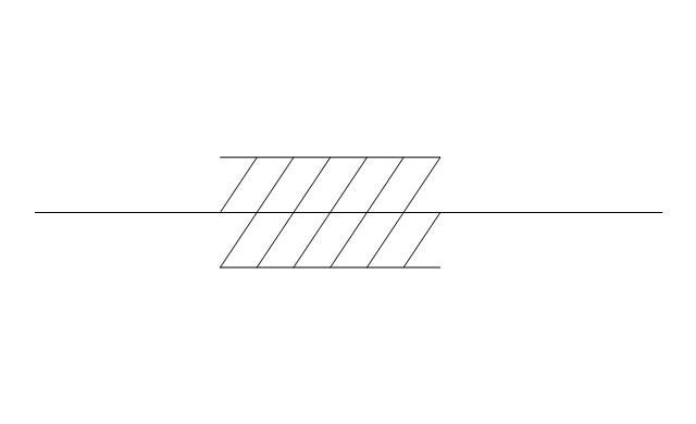
Lagged
Bellows
Flow indication
Flow indication 2
Reducer
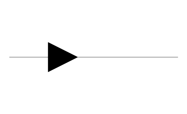
Reducer,arrow
Pipe bore change
Flexibility provision
Sleeve extension
Flow restrictor
Elbow 45
Elbow 90
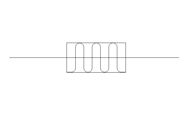
Heated or cooled
Pneumatic line
Signal line
Electric line
Hydraulic line
Capillary line
Internal connection
Route radiation
Mechanical linkage
Electrical device
Vibratory device
Weight device
Spray device
Rotary motion
Stirring / fan
Access points
Trap
Expansion loop
Flexible hose
Flexible hose, flanged
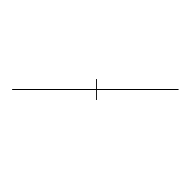
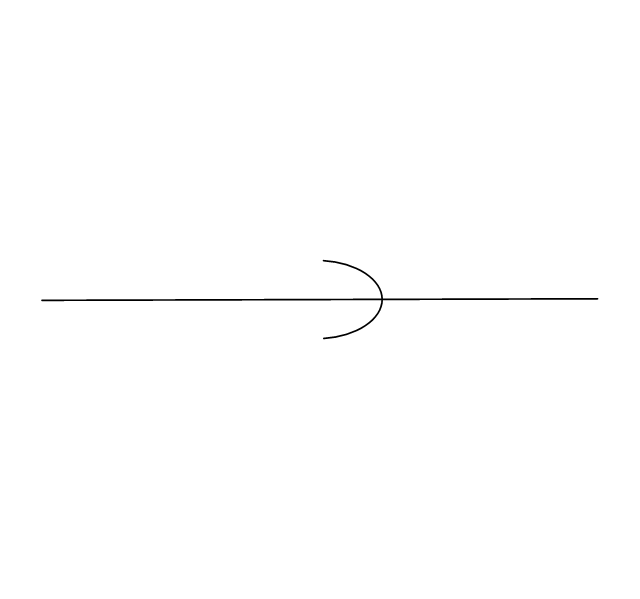
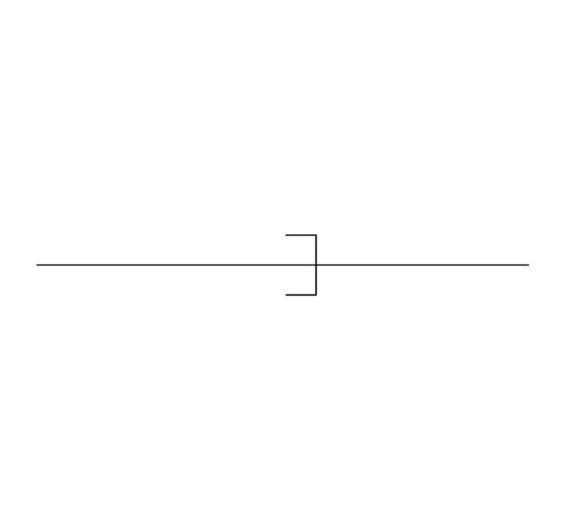
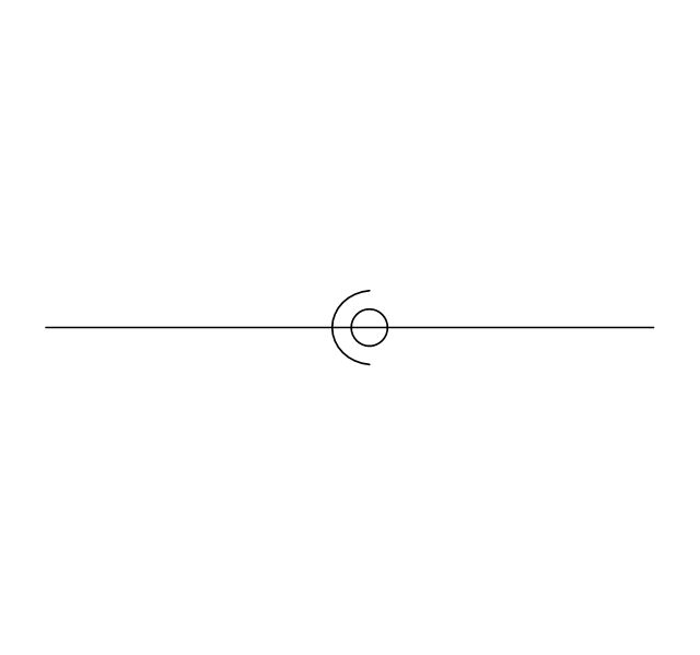
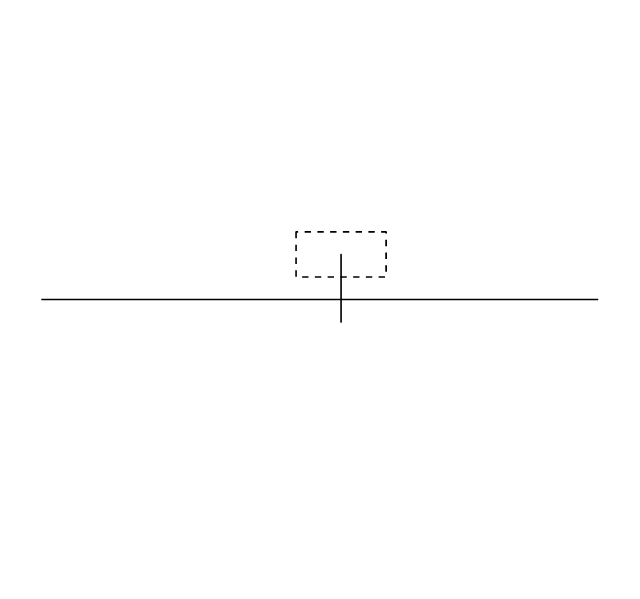
The vector stencils library "Pipes 1" contains 28 symbols of pipes. Use it for drawing plumbing and piping building plans, schematic diagrams, blueprints, or technical drawings of waste water disposal systems, hot and cold water supply systems in the ConceptDraw PRO diagramming and vector drawing software extended with the Plumbing and Piping Plans solution from the Building Plans area of ConceptDraw Solution Park.
General joint
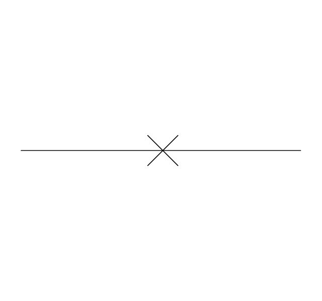
Butt weld
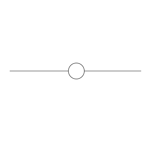
Soldered / solvent
Screwed joint
Socket and spigot
Sleeve joint
Socket weld
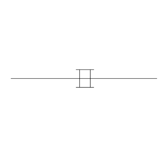
Flanged / bolted

Swivel joint
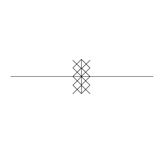
Electrically bonded
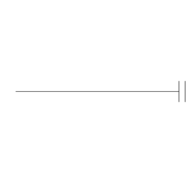
Electrically insulated
End caps 1
End caps 2
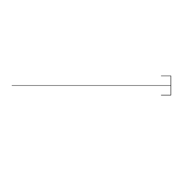
End caps 3
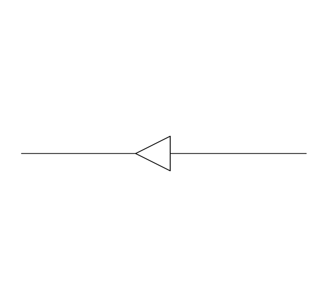
Strainer

Separator
Exhaust silencer
Drain silencer
Open vent
Syphon drain
Hydrant
Tundish
Bell mouth
Exhaust head
Bursting disc
Flame arrester
Y strainer
Liquid seal open/closed
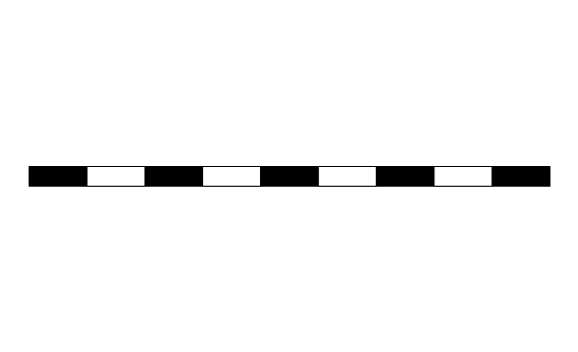
The vector stencils libraries "Pipes 1" and "Pipes 2" contain 28 and 48 pipe, tubing and fitting symbols, respectively.
"Pipe is hollow cylinder used to conduct or transfer fluids (liquids and gases) from one place to other place. The main difference between pipe and tube is the critical dimension used to describe the pipe size or the tube size. For pipe, internal diameter (ID) roughly corresponds to the nominal pipe size for standard wall thickness. For tube, the outer diameter (OD) closely corresponds to the tube size. In current European standards pipes and tubes are nowadays described as outside diameter by wall thickness. The three standard types of pipe ends used in the piping industriesare; Plain Ends (PE), Threaded Ends (TE) and Beveled Ends (BE). In the past, many types of material have been used in conveying water from one point to another. Masonry and wood were probably the first materials used. Plastics are the newest, and are now being used quite extensively." [Piping. Wikipedia]
Use the design elements libraries "Pipes 1" and "Pipes 2" for drawing plumbing and piping building plans, schematic diagrams, blueprints, or technical drawings of waste water disposal systems, hot and cold water supply systems using the ConceptDraw PRO diagramming and vector drawing software.
The shapes libraries "Pipes 1" and "Pipes 2" are contained in the Plumbing and Piping Plans solution from the Building Plans area of ConceptDraw Solution Park.
Piping symbols
.png--diagram-flowchart-example.png)
Building Drawing. Design Element: Piping Plan


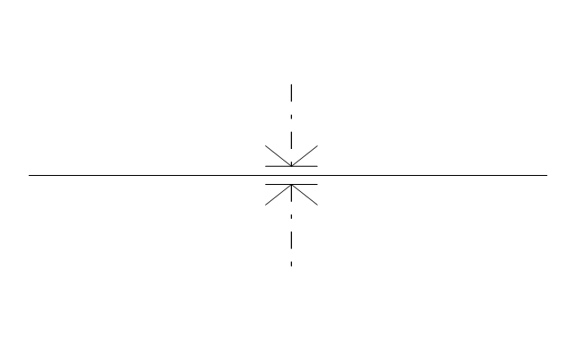
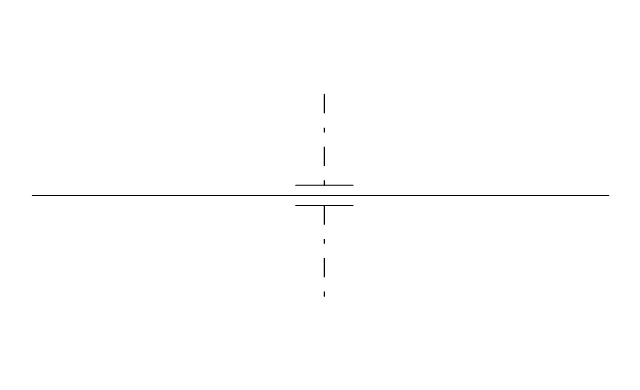
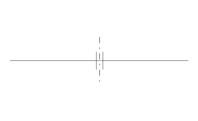
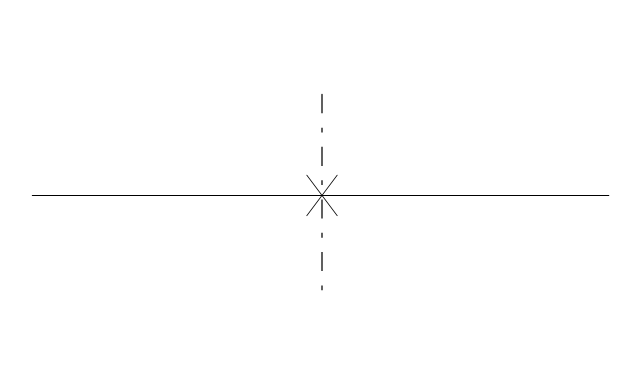
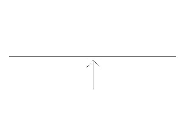
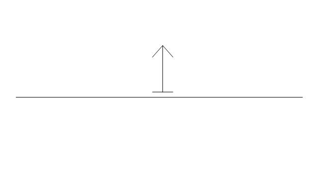
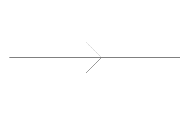
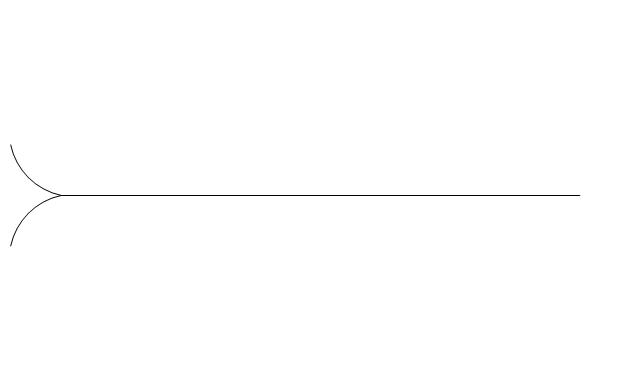
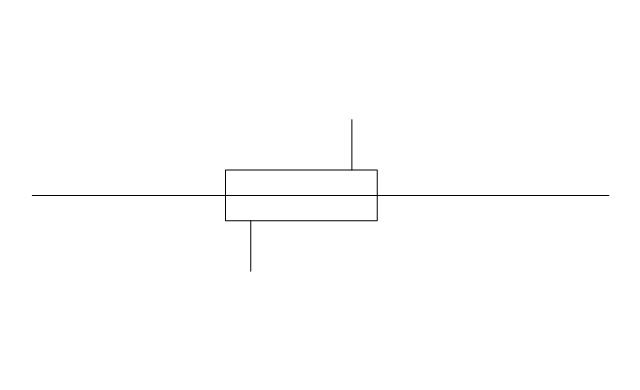
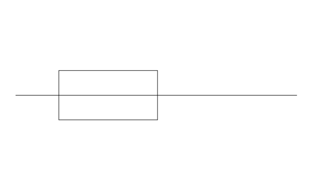
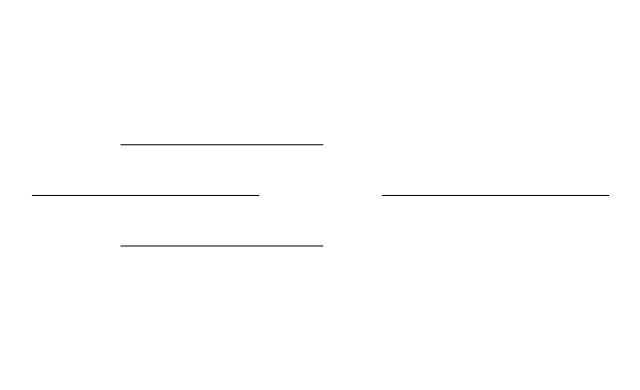
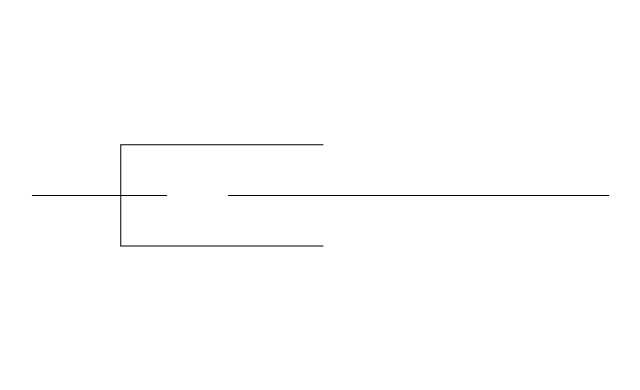
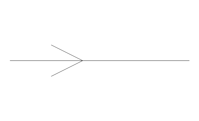
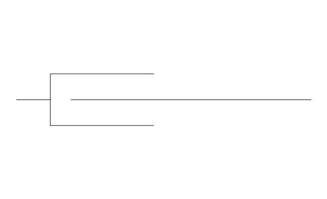
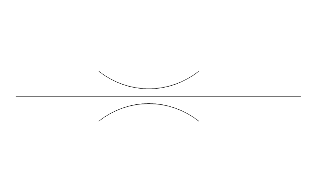
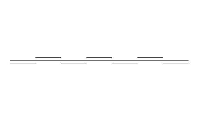
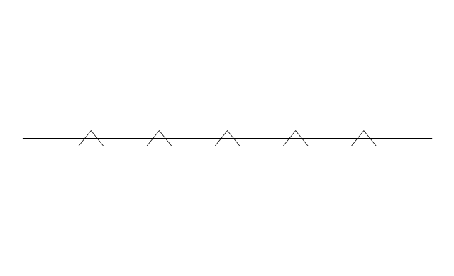
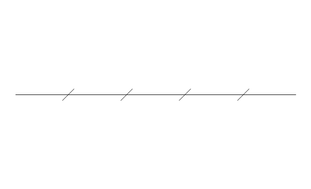
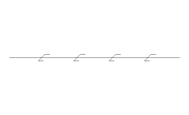
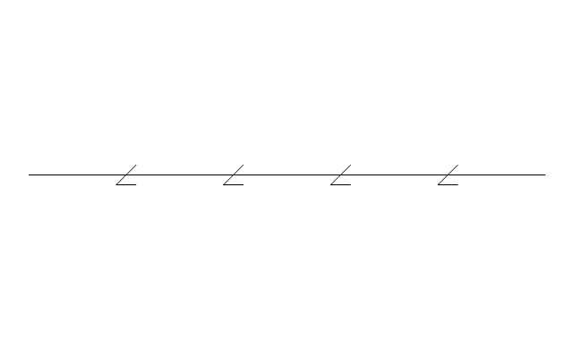
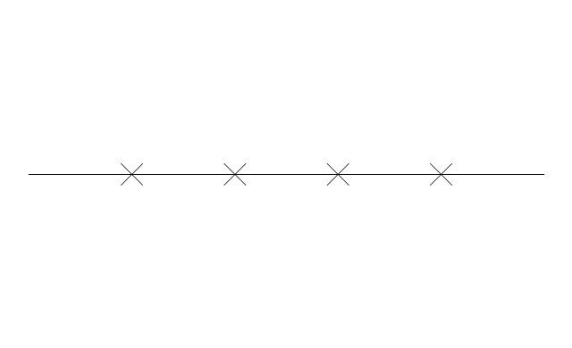
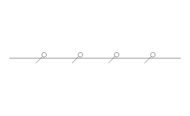
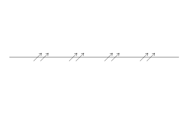
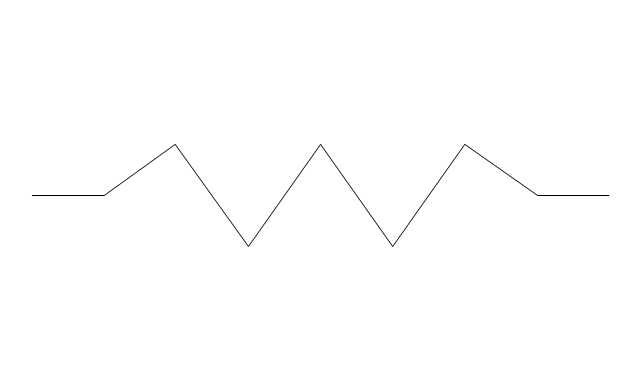
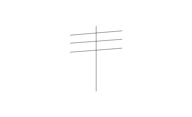
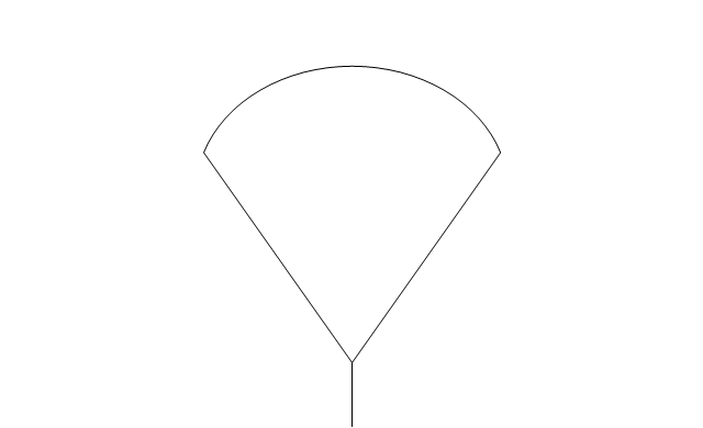
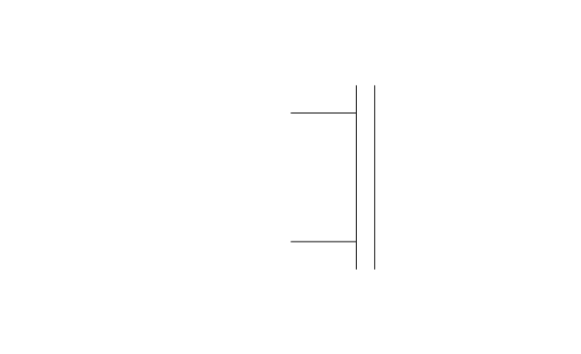
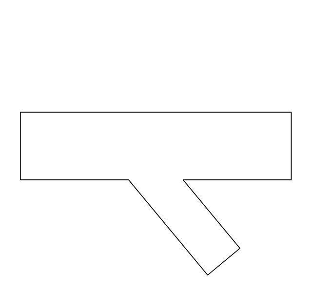
This engineering drawing present weld type symbols and fillet weld symbols.
The weld type symbol is typically placed above or below the center of the reference line, depending on which side of the joint it's on. The symbol is interpreted as a simplified cross-section of the weld.
"Fillet welding refers to the process of joining two pieces of metal together whether they be perpendicular or at an angle. These welds are commonly referred to as Tee joints which are two pieces of metal perpendicular to each other or Lap joints which are two pieces of metal that overlap and are welded at the edges. The weld is aesthetically triangular in shape and may have a concave, flat or convex surface depending on the welder’s technique. Welders use fillet welds when connecting flanges to pipes, welding cross sections of infrastructure, and when fastening metal by bolts isn't strong enough." [Fillet weld. Wikipedia]
The engineering drawing example Welding symbols is included in the Mechanical Engineering solution from Engineering area of ConceptDraw Solution Park.
Welding joint symbols

Piping and Instrumentation Diagram Software

- Design elements - Pipes ( part 1) | Welding symbols | Pipes 2 ...
- Building Drawing Design Element: Piping Plan | Electrical Design ...
- Welding symbols | Design elements - Pipes ( part 1) | Mechanical ...
- Welding Piping Joint Symbols In Pdf For Mechanical Drafting
- Pipes 2 - Vector stencils library | Design elements - Pipes ( part 2 ...
- Pipe Welding Drawing Symbols
- Design elements - Valves and fittings | Design elements - Pipes ( part ...
- Engineering Drawing Handsaw
- Mechanical Engineering | Pipes 2 - Vector stencils library ...
- Design elements - Pipes ( part 1) | Welding symbols | Design ...