Bubble diagrams in Landscape Design with ConceptDraw DIAGRAM
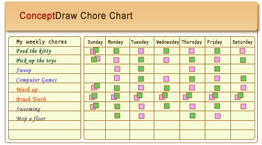
Bubble Diagrams are the charts with a bubble presentation of data with obligatory consideration of bubble's sizes. They are analogs of Mind Maps and find their application at many fields, and even in landscape design. At this case the bubbles are applied to illustrate the arrangement of different areas of future landscape design, such as lawns, flowerbeds, playgrounds, pools, recreation areas, etc. Bubble Diagram helps to see instantly the whole project, it is easy for design and quite informative, in most cases it reflects all needed information. Often Bubble Diagram is used as a draft for the future landscape project, on the first stage of its design, and in case of approval of chosen design concept is created advanced detailed landscape plan with specification of plants and used materials. Creation of Bubble Diagrams for landscape in ConceptDraw DIAGRAM software is an easy task thanks to the Bubble Diagrams solution from "Diagrams" area. You can use the ready scanned location plan as the base or create it easy using the special ConceptDraw libraries and templates.Chore charts with ConceptDraw DIAGRAM
Chore chart. Draw perfect-looking chore chart. Free chore chart samples. All about chore charts.
 HR Flowcharts
Human resource management diagrams show recruitment models, the hiring process and human resource development of human resources.
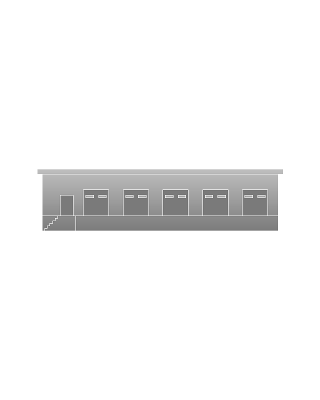
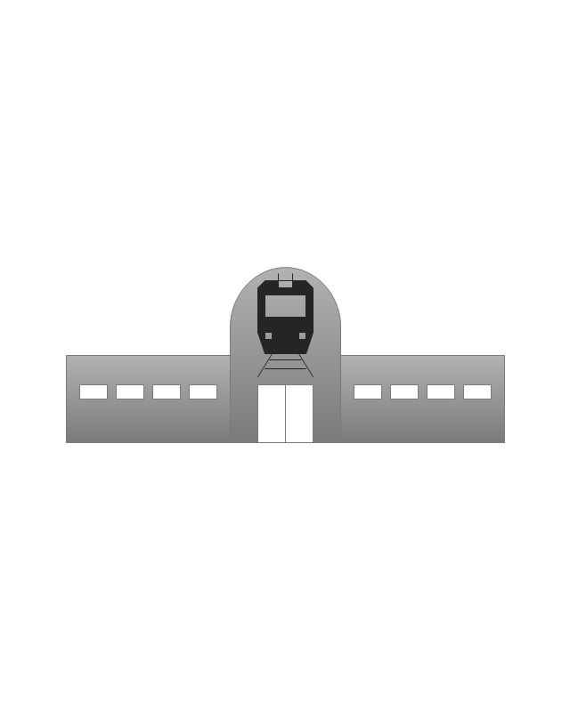
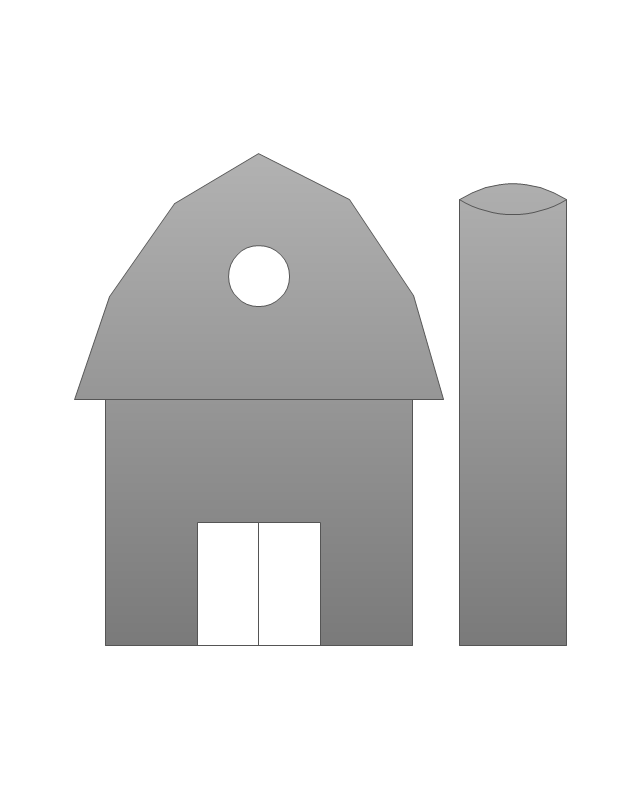
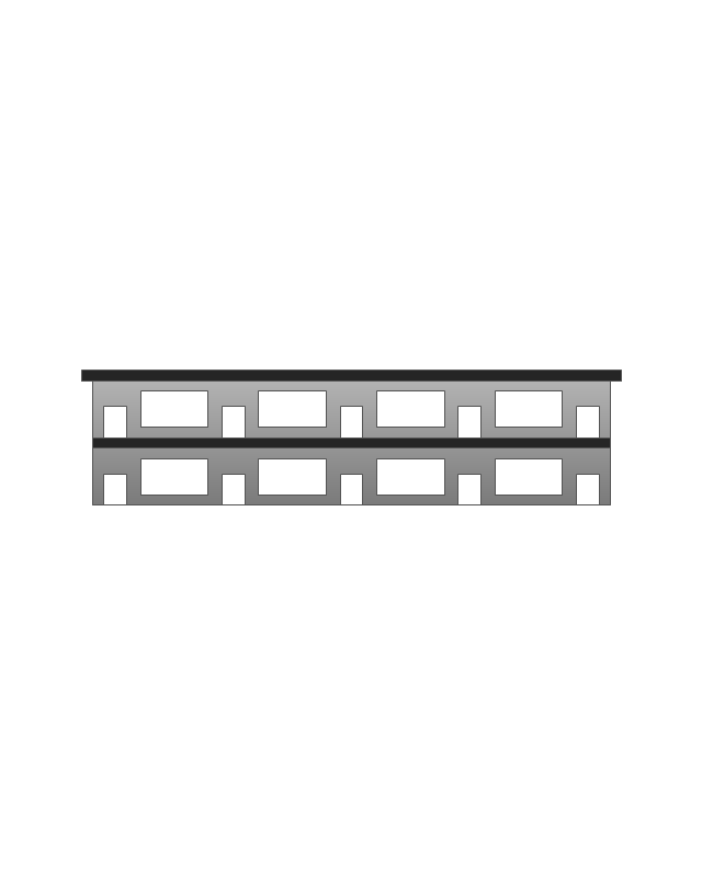
The vector stencils library "Landmarks" contains 69 landmark symbols of buildings, waterways, scale and directional indicators for labeling transportation and directional maps, road and route maps, street and transit maps, locator and tourist maps.
The pictograms example "Landmarks - Vector stencils library" was created using the ConceptDraw PRO diagramming and vector drawing software extended with the Directional Maps solution from the Maps area of ConceptDraw Solution Park.
The pictograms example "Landmarks - Vector stencils library" was created using the ConceptDraw PRO diagramming and vector drawing software extended with the Directional Maps solution from the Maps area of ConceptDraw Solution Park.
ConceptDraw Arrows10 Technology
Connecting objects manually in ConceptDraw DIAGRAM is a snap: - points; - Connecting groups of objects; - Auto-routing; - Connectors text; - Snap to Guides ; - Quick.- Symbol Start
- Basic Flowchart Symbols and Meaning | Process Flowchart | How To ...
- Mechanical Drawing Symbols | Pneumatic 5-ported 3-position valve ...
- Which Symbol Represents The Starting Or Stopping Point Of A ...
- Basic Flowchart Symbols and Meaning | Euclidean algorithm ...
- Design elements - Pipes ( part 1) | Design elements - Valves and ...
- Interior Design Piping Plan - Design Elements | Welding symbols ...
- Basic Flowchart Symbols and Meaning | Process Flowchart ...
- Air Conditioner Symbol Floor Plan
- Elements location of a welding symbol | Design elements - Pipes ...
- Basic Flowchart Symbols and Meaning | Flow Chart Symbols ...
- Ventilation Symbols Drawings
- Mechanical Drawing Symbols | Design elements - Valve assembly ...
- Electrical Symbols — Thermo | Electrical Symbols — Resistors ...
- Basic Flowchart Symbols and Meaning | Flow Chart Symbols ...
- Interior Design Piping Plan - Design Elements | Welding symbols ...
- Welding symbols | Interior Design Piping Plan - Design Elements ...
- Fitting Joint Symbol
- Pipe Fittings Symbols Reducer
- Diagramming Sentences Symbols

