HelpDesk
How to Create a Mechanical Diagram
Mechanical Engineering drawing is a type of technical drawing that helps analyze complex engineering systems. Mechanical Engineering diagrams are often a set of detailed drawings used for engineering or construction projects. Making Mechanical Engineering diagram involves many different elements that can be managed using ConceptDraw PRO. You can design elements for drawing parts, assembly, pneumatic, and hydraulic systems for mechanical engineering. With ConceptDraw PRO you can easily create and communicate the Mechanical Engineering diagram of any complexity.
 Mechanical Engineering
This solution extends ConceptDraw PRO v.9 mechanical drawing software (or later) with samples of mechanical drawing symbols, templates and libraries of design elements, for help when drafting mechanical engineering drawings, or parts, assembly, pneumatic,
 Seven Basic Tools of Quality
Manage quality control in the workplace, using fishbone diagrams, flowcharts, Pareto charts and histograms, provided by the Seven Basic Tools of Quality solution.
Process Flowchart
The main reason of using Process Flowchart or PFD is to show relations between major parts of the system. Process Flowcharts are used in process engineering and chemical industry where there is a requirement of depicting relationships between major components only and not include minor parts. Process Flowcharts for single unit or multiple units differ in their structure and implementation. ConceptDraw PRO is Professional business process mapping software for making Process flowcharts, Process flow diagram, Workflow diagram, flowcharts and technical illustrations for business documents and also comprehensive visio for mac application. Easier define and document basic work and data flows, financial, production and quality management processes to increase efficiency of your business with ConcepDraw PRO. Business process mapping software with Flowchart Maker ConceptDraw PRO includes extensive drawing tools, rich examples and templates, process flowchart symbols and shape libraries, smart connectors that allow you create the flowcharts of complex processes, process flow diagrams, procedures and information exchange. Process Flowchart Solution is project management workflow tools which is part ConceptDraw Project marketing project management software. Drawing charts, diagrams, and network layouts has long been the monopoly of Microsoft Visio, making Mac users to struggle when needing such visio alternative like visio for mac, it requires only to view features, make a minor edit to, or print a diagram or chart. Thankfully to MS Visio alternative like ConceptDraw PRO software, this is cross-platform charting and business process management tool, now visio alternative for making sort of visio diagram is not a problem anymore however many people still name it business process visio tools.
HelpDesk
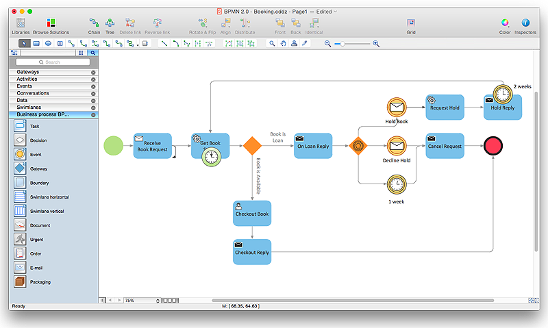
How to Create a BPMN Diagram Using ConceptDraw PRO
Business Process Modeling Notation (BPMN) is a method of illustrating business processes in the form of a diagram. The most effective method of creating or analyzing a business process is to visually interpret the steps using a business process diagram, flowchart or workflow. This is known as business process modeling, and will be performed within a company by a team who have detailed knowledge of company process, and analysts with expertise in the modeling discipline. The objective is often to increase production or lower costs — by modeling the process initially using a flowchart, inefficiencies and problems can be spotted before committing to a decision or strategy. You can create BPMN diagrams using the ConceptDraw PRO diagramming tools. ConceptDraw have designed a solution that combines BPMN v2.0 methodology and graphical notification into one powerful package. The Business Process Diagrams solution from ConceptDraw Solution Park provides a comprehensive collection of vector- Floor Plans For Computer Factories
- Floor Plan Of Computer Assembling Company
- Computer Shop Floor Plan Design With Dimensions And Wiring
- Design elements - Machines and equipment | Hotel Plan . Hotel Plan ...
- Process Flowchart | Sales Flowcharts | Floor Plans | Work Floe In ...
- Cafe and Restaurant Floor Plan | How To Create Restaurant Floor ...
- Office Layout Plans | How To Draw Building Plans | Electrical ...
- Hotel Network Topology Diagram | UML Class Diagram Example ...
- Basic Flowchart Symbols and Meaning | Technical Drawing ...
- How To Draw Building Plans | How to Create a Floor Plan Using ...
- Hotel Plan . Hotel Plan Examples | Computer and Networks Area ...
- Office wireless network plan | Hotel Plan . Hotel Plan Examples ...
- Interior Design Office Layout Plan Design Element | Office plan ...
- Factory layout floor plan | Plant Layout Plans | Building Plans Area ...
- Plumbing and Piping Plans | How to Create a Floor Plan Using ...
- Factory layout floor plan | Plant Layout Plans | How To Draw ...
- Design elements - Network layout floorplan | Create Floor Plans ...
- Entity Relationship Diagram Symbols and Meaning ERD Symbols ...
- Factory layout floor plan
- How To Create Restaurant Floor Plan in Minutes | Cafe and ...


