Network Printer
Special libraries of highly detailed, accurate shapes and computer graphics, servers, hubs, switches, printers, mainframes, face plates, routers etc.
Network Hubs
Special libraries of highly detailed, accurate shapes and computer graphics, servers, hubs, switches, printers, mainframes, face plates, routers etc.
Network Gateway Router
Special libraries of highly detailed, accurate shapes and computer graphics, servers, hubs, switches, printers, mainframes, face plates, routers etc.
Network Layout
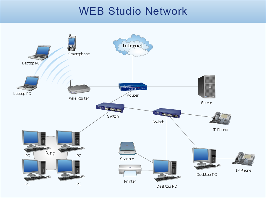
The Network Layout Diagram visually illustrates the arrangement of computers, nodes and other network appliances, such as servers, printers, routers, switches, hubs, and their relationships between each other. The network layout and placement of servers greatly influence on the network security and network performance. Elaboration of robust Network Layout Diagram is especially important when visualizing already existing network in order to understand its complexity; when troubleshooting the network issues; designing, documenting and implementing new network configurations; extending, modifying, or moving an existing network to other location. Through the careful thinking the network plan and designing the clear Network Layout Diagram, you can be confident in result on the stage of network implementation and to solve faster the problems appearing in network infrastructure. ConceptDraw DIAGRAM enhanced with Computer Network Diagrams solution from Computer and Networks area perfectly suits for drawing Network Layout Diagrams for different network topologies.
Computer network documentation is important part of industry best practices. It used by network engineers, service providers and value-added resellers (VARs) for documenting corporate and customers' networks. Network documentation is very helpful in technical maintenance, troubleshooting, upgrading and IT specialist training processes.
The basic computer network diagram example was created using the ConceptDraw PRO diagramming and vector drawing software extended with the Computer and Networks solution from the Computer and Networks area of ConceptDraw Solution Park.
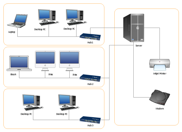
The basic computer network diagram example was created using the ConceptDraw PRO diagramming and vector drawing software extended with the Computer and Networks solution from the Computer and Networks area of ConceptDraw Solution Park.
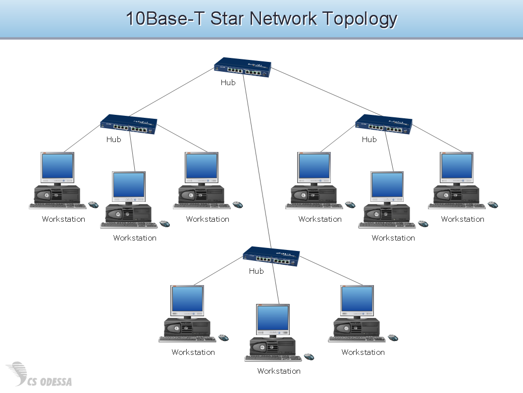
"Physical topology refers to the placement of the network's various components, including device location and cable installation...
The shape of the cabling layout used to link devices is called the physical topology of the network. This refers to the layout of cabling, the locations of nodes, and the interconnections between the nodes and the cabling. The physical topology of a network is determined by the capabilities of the network access devices and media, the level of control or fault tolerance desired, and the cost associated with cabling or telecommunications circuits." [Network topology. Wikipedia]
This physical LAN diagram example was created using the ConceptDraw PRO diagramming and vector drawing software extended with the Computer and Networks solution from the Computer and Networks area of ConceptDraw Solution Park.
Used Solutions
- Network Printer | Network Diagram Software | Network diagrams ...
- Network Printer | Physical LAN topology diagram | Network Diagram ...
- How To use Switches in Network Diagram | Star Network Topology ...
- Connecting Diagram Of Adsl Switch Printer Server And Pc
- Network Printer | Point to Point Network Topology | Network Diagram ...
- Layout Of Lan With 10 Pc And A Network Printer
- Network Printer | Wireless access point - Network diagram | Wireless ...
- How To Connect Local Printer In Pc Flow Chart
- Physical LAN and WAN diagram - Template | Network Diagram ...
- Home area networks (HAN). Computer and Network Examples ...
- How to Draw a Computer Network Diagrams | Process Flowchart ...
- Wireless router network diagram | Computer Network Diagrams ...
- Wired Connection Diagram
- Diagram Of A Computer Connected To Printer
- Network Printer | Fully Connected Network Topology Diagram ...
- Network Printer | Logical network diagram - Vector stencils library ...
- Hotel Network Topology Diagram | Computer network diagram ...
- Network Printer | Design Element: Computer and Network for ...
- Star Network Topology | Network Topologies | Fully Connected ...
- Computer network - Vector stencils library | Network Glossary ...


