Process Engineering
Process Flow Diagram Symbols

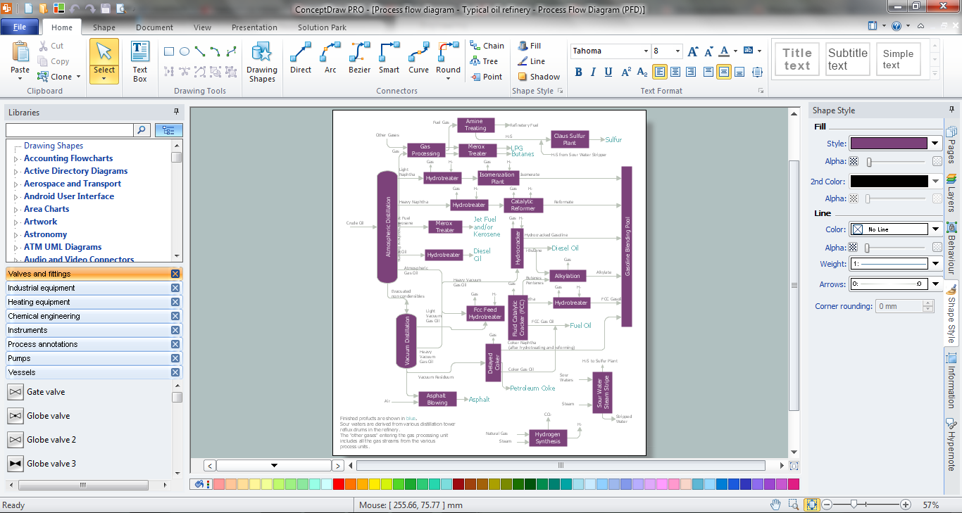
Chemical Engineering

The vector stencils library "Industrial equipment" contains 81 symbols of pumps, compressors, fans, turbines, and power generators.
Use these shapes to design pumping systems, air and fluid compression systems, and industrial process diagrams.
"Process engineering focuses on the design, operation, control, and optimization of chemical, physical, and biological processes. Process engineering encompasses a vast range of industries, such as chemical, petrochemical, mineral processing, advanced material, food, pharmaceutical, and biotechnological industries. The application of systematic computer-based methods to process engineering is process systems engineering." [Process engineering. Wikipedia]
The example "Design elements - Industrial equipment" was created using the ConceptDraw PRO diagramming and vector drawing software extended with the Chemical and Process Engineering solution from the Engineering area of ConceptDraw Solution Park.
Industrial equipment symbols

Audit Flowchart Symbols

Cisco Security. Cisco icons, shapes, stencils and symbols

The vector stencils library "Fault tree analysis diagrams" contains 12 symbols for drawing Fault Tree Analysis (FTA) diagrams.
"Fault tree analysis (FTA) is a top down, deductive failure analysis in which an undesired state of a system is analyzed using Boolean logic to combine a series of lower-level events. This analysis method is mainly used in the fields of safety engineering and reliability engineering to understand how systems can fail, to identify the best ways to reduce risk or to determine (or get a feeling for) event rates of a safety accident or a particular system level (functional) failure. FTA is used in the aerospace, nuclear power, chemical and process, pharmaceutical, petrochemical and other high-hazard industries; but is also used in fields as diverse as risk factor identification relating to social service system failure.
In aerospace, the more general term "system Failure Condition" is used for the "undesired state" / Top event of the fault tree. These conditions are classified by the severity of their effects. The most severe conditions require the most extensive fault tree analysis. These "system Failure Conditions" and their classification are often previously determined in the functional Hazard analysis." [Fault tree analysis. Wikipedia]
The shapes example "Fault tree analysis diagrams" was created using the ConceptDraw PRO diagramming and vector drawing software extended with the Fault Tree Analysis Diagrams solution from the Engineering area of ConceptDraw Solution Park.
FTA diagram symbols

Living Room. Piano in plan

Process Flow Diagram

Fault Tree Analysis Software

Processing Flow Chart

ConceptDraw DIAGRAM enhanced with Flowcharts Solution from the "Diagrams" Area of ConceptDraw Solution Park is a powerful Processing Flow Chart software which will help save lots of your time.
Create Floor Plans Easily with ConceptDraw DIAGRAM


IDEF4 Standard

- Petrochemical Equipment Symbols
- Equipments And Their Symbols In Chemical Industry
- Engineering Symbols
- Technical Drawing Software | Chemical Engineering | Process Flow ...
- Process Flowchart | Process Engineering | Design elements ...
- Process Flow Diagram Symbols | Chemical Engineering | Cisco ...
- Process Flowchart | Process Engineering | Process Flow Diagram ...
- Symbols Used In Pharmaceutical Engineering
- Process Flowchart | Design elements - Chemical engineering ...
- Chemical and Process Engineering | Process Flow Diagram ...
- Symbols Of Food Engineering Equipments
- Crude oil distillation unit - PFD | Process flow diagram (PFD ...
- Mechanical Drawing Symbols | Chemical and Process Engineering ...
- Process Flow Diagram | Chemical and Process Engineering ...
- Process Flowchart | Process Flow Diagram Symbols | Interior Design ...
- Chemical Engineering | Process Flowchart | Electrical Drawing ...
- Engineering Quality Control Drawing Symbols
- Mechanical Engineering Name Symbol
- Valve Symbols Chart
- Mechanical Drawing Symbols | Mechanical Engineering | Process ...