Electrical Symbols, Electrical Diagram Symbols

Electrical Symbols — Semiconductor Diodes

The vector stencils library "Semiconductor diodes" contains 24 symbols of semiconductor diodes.
Use these shapes for drawing electronic schematics and circuit diagrams in the ConceptDraw PRO diagramming and vector drawing software extended with the Electrical Engineering solution from the Engineering area of ConceptDraw Solution Park.
www.conceptdraw.com/ solution-park/ engineering-electrical
Use these shapes for drawing electronic schematics and circuit diagrams in the ConceptDraw PRO diagramming and vector drawing software extended with the Electrical Engineering solution from the Engineering area of ConceptDraw Solution Park.
www.conceptdraw.com/ solution-park/ engineering-electrical
Diode, env
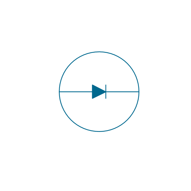
Diode

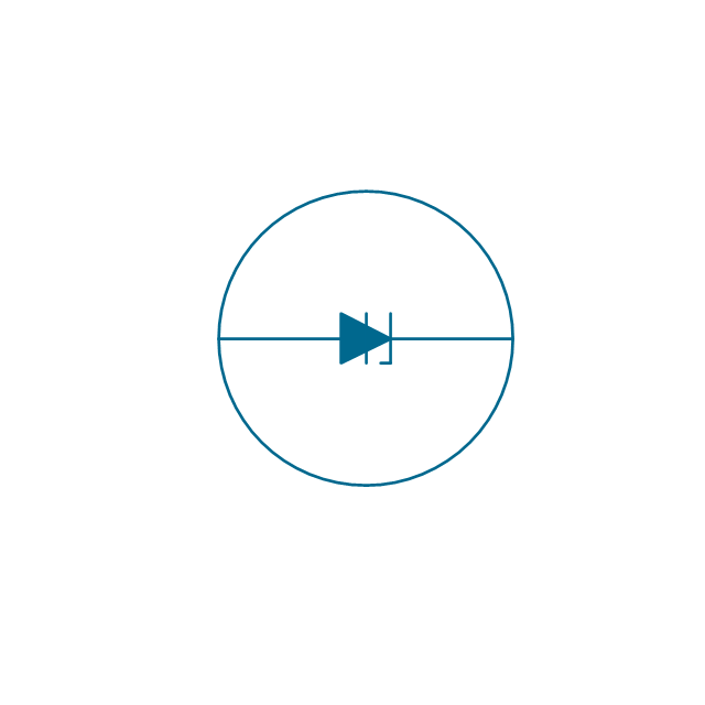
Diode, reverse blocking, env

Diode, reverse blocking

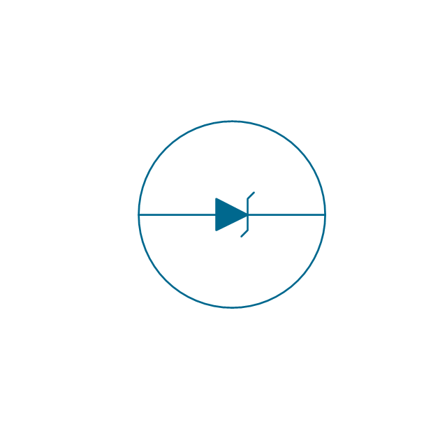
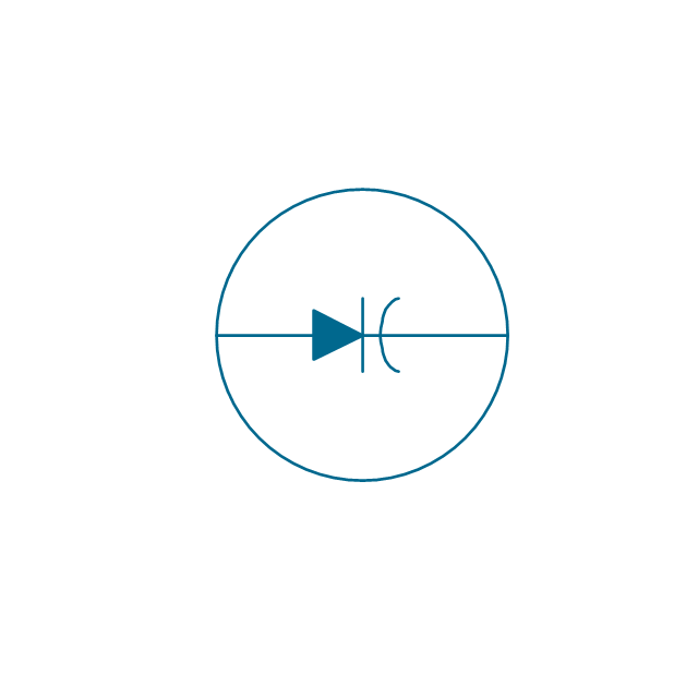
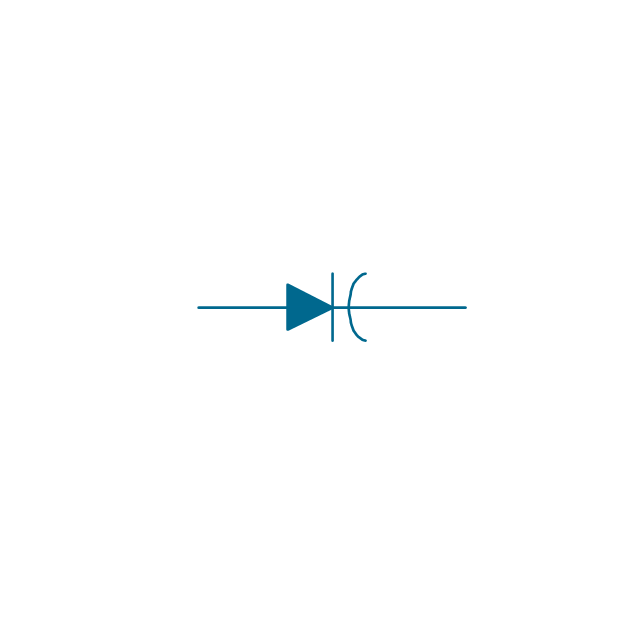
Diode, reverse conducting, env
Diode, reverse conducting

Tunnel diode, env

Tunnel diode

Zener diode, env
Zener diode

Backward diode, env
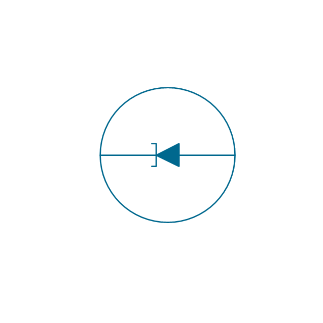
Backward diode

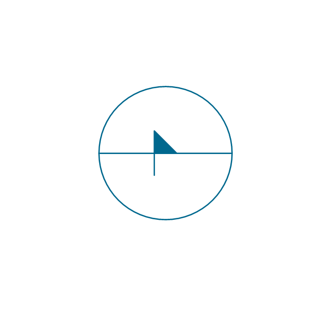
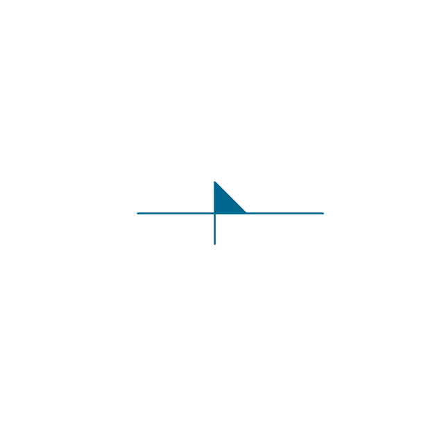
Varactor, env
Varactor
Four layer diode, env
Four layer diode
LED, env
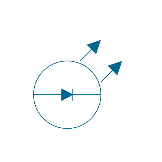
LED
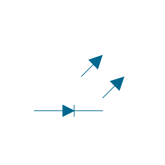
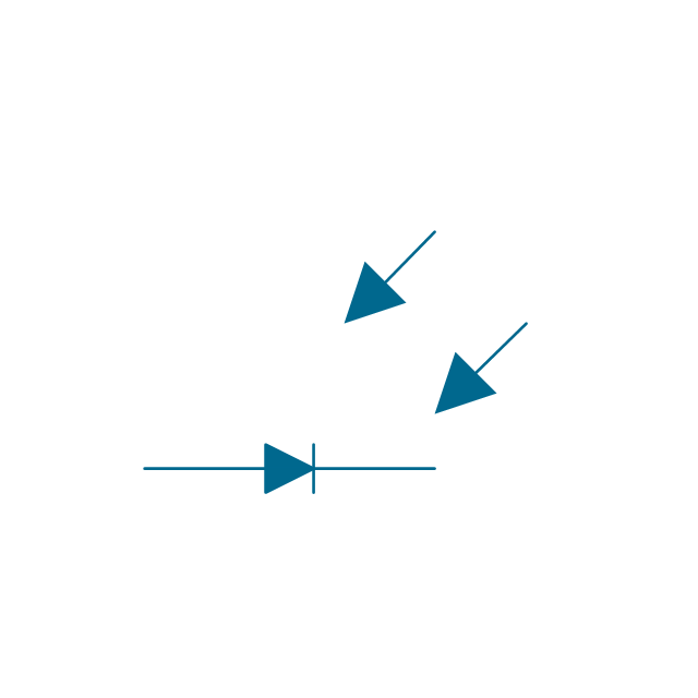
Photo-diode, env
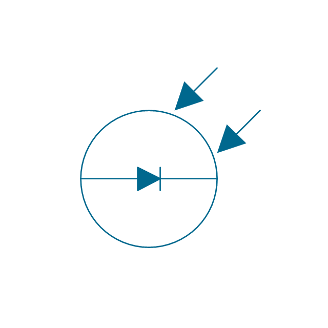
Photo-diode
Breakdown diode, uni-directional, env
Breakdown diode, uni-directional

Breakdown diode, bi-directional, env

Breakdown diode, bi-directional

Electrical Drawing Software and Electrical Symbols

Electrical Symbols — VHF UHF SHF

Circuits and Logic Diagram Software

Electrical Symbols — Switches and Relays

Electrical Symbols — Terminals and Connectors

Electrical Symbols — Delay Elements

- Design elements - Logic gate diagram | Resistor And Diode Symbols
- Electrical Symbols , Electrical Diagram Symbols | Electrical Symbols ...
- Electrical Symbols — Semiconductor Diodes | Design elements ...
- Symbol For Semiconductor Diode
- Design elements - Semiconductor diodes | Design elements - Delay ...
- Design elements - Semiconductor diodes | Electrical Symbols ...
- Electrical Symbols — Semiconductor Diodes | Electrical Symbols ...
- Electrical Symbols , Electrical Diagram Symbols | All Electrical ...
- Semiconductor Diode Symbol
- Circuit Symbol Of Rectifier Diode