 Plumbing and Piping Plans
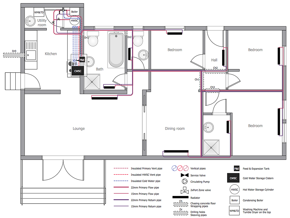
Plumbing and Piping Plans solution extends ConceptDraw PRO v10.2.2 software with samples, templates and libraries of pipes, plumbing, and valves design elements for developing of water and plumbing systems, and for drawing Plumbing plan, Piping plan, PVC Pipe plan, PVC Pipe furniture plan, Plumbing layout plan, Plumbing floor plan, Half pipe plans, Pipe bender plans.
 Engineering
This solution extends ConceptDraw PRO v9.4 with the ability to visualize industrial systems in electronics, electrical, chemical, process, and mechanical engineering.
 ConceptDraw Solution Park
ConceptDraw Solution Park collects graphic extensions, examples and learning materials
 Mechanical Engineering
This solution extends ConceptDraw PRO v.9 mechanical drawing software (or later) with samples of mechanical drawing symbols, templates and libraries of design elements, for help when drafting mechanical engineering drawings, or parts, assembly, pneumatic,
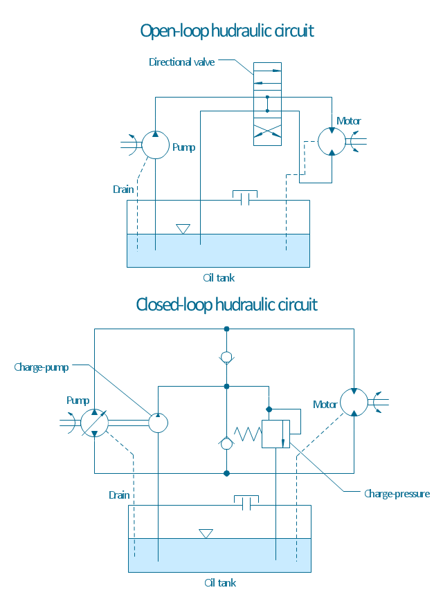
"A hydraulic circuit is a system comprising an interconnected set of discrete components that transport liquid. The purpose of this system may be to control where fluid flows (as in a network of tubes of coolant in a thermodynamic system) or to control fluid pressure (as in hydraulic amplifiers).
... hydraulic circuit theory works best when the elements (passive component such as pipes or transmission lines or active components such as power packs or pumps) are discrete and linear. This usually means that hydraulic circuit analysis works best for long, thin tubes with discrete pumps, as found in chemical process flow systems or microscale devices." [Hydraulic circuit. Wikipedia]
The engineering drawing example "Hydraulic circuits" was redrawn using ConceptDraw PRO diagramming and vector drawing software from the Wikimedia Commons file: Hydraulic circuits.png.
[commons.wikimedia.org/ wiki/ File:Hydraulic_ circuits.png]
This file is licensed under the Creative Commons Attribution-Share Alike 3.0 Unported license.
[creativecommons.org/ licenses/ by-sa/ 3.0/ deed.en]
The engineering drawing example "Hydraulic circuits" is included in the Mechanical Engineering solution from the Engineering area of ConceptDraw Solution Park.
HelpDesk
How to Create a Residential Plumbing Plan
Planning a construction, or making a building plan you have take into account the plumbing and piping peculiarities. You need to make plan that shows the layout and connection of pipers, location of plumbing equipment, etc. Even with a plan changes may be necessary as you work, but a well-done plumbing and piping plan surely makes your work much easier. CnceptDraw Plumbing and Piping Plans solution provides you with the ability to create plumbing and piping plan that use official plumbing symbols. Making detailed Plumbing and Piping Plan will save time and costs. Also, drawing the Plumbing and Piping layout helps you considered through the project in detail, which may enable you to detect things that be probably missed. At least it certainly will minimize visits to the plumbing supply store and save your money. A clear, professional-looking Plumbing and Piping Plan also will make your communication with a building contractor more productive.- Mechanical Engineer Drawing For Pipe Line
- Pipeline Welding Drawings
- Mechanical Engineering | Piping and Instrumentation Diagram ...
- Different Mechanical Symbols Of Pipeline Used In Engineering
- Mechanical Drawing Symbols | Piping and Instrumentation Diagram ...
- Building Drawing Design Element: Piping Plan | Technical Drawing ...
- Welder Pipe Line Diagram Image
- How To Make Pipe Line Engineering Drawing
- Interior Design Piping Plan - Design Elements | Mechanical ...
- Building Drawing Design Element: Piping Plan | Plumbing and ...
- Mechanical Drawing Symbols | Mechanical Drawing Software ...
- Mechanical Drawing Symbols | Interior Design Piping Plan - Design ...
- Mechanical Drawing Symbols | Mechanical Engineering | Welding ...
- Electronics Mechanics Engineering Drawing Line
- Basic Mechanical Piping Symbols
- Mechanical Engineering And Plumbing Pipeline Drawing In A Building
- Mechanical Drawing Symbols | Interior Design Piping Plan - Design ...
- Mechanical Drawing Symbols | Mechanical Engineering | Piping ...
- Mechanical Drawing Symbols | Process Flow Diagram Symbols ...

