 Plumbing and Piping Plans
Plumbing and Piping Plans solution extends ConceptDraw PRO v10.2.2 software with samples, templates and libraries of pipes, plumbing, and valves design elements for developing of water and plumbing systems, and for drawing Plumbing plan, Piping plan, PVC Pipe plan, PVC Pipe furniture plan, Plumbing layout plan, Plumbing floor plan, Half pipe plans, Pipe bender plans.
 Chemical and Process Engineering
This chemical engineering solution extends ConceptDraw PRO v.9.5 (or later) with process flow diagram symbols, samples, process diagrams templates and libraries of design elements for creating process and instrumentation diagrams, block flow diagrams (BFD
"A piping and instrumentation diagram/ drawing (P&ID) is a diagram in the process industry which shows the piping of the process flow together with the installed equipment and instrumentation. ...
P&IDs play a significant role in the maintenance and modification of the process that it describes. It is critical to demonstrate the physical sequence of equipment and systems, as well as how these systems connect. During the design stage, the diagram also provides the basis for the development of system control schemes, allowing for further safety and operational investigations, such as a Hazard Analysis and Operability Study...
For processing facilities, it is a pictorial representation of:
Key piping and instrument details,
Control and shutdown schemes,
Safety and regulatory requirements,
Basic start up and operational information." [Piping and instrumentation diagram. Wikipedia]
The piping and instrumentation diagram template for the ConceptDraw PRO diagramming and vector drawing software is included in the Chemical and Process Engineering solution from the Engineering area of ConceptDraw Solution Park.
HelpDesk
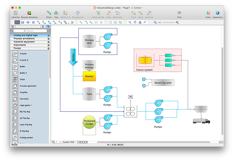
How to Draw a Process Flow Diagram in ConceptDraw PRO
Process Flow diagrams are used in chemical and process engineering to show the flow of chemicals and the equipment involved in the process. When it comes to creating a process flow diagram, it's important to use software that is capable of describing a wide range of processes, using techniques and graphical notation that are easily recognized by engineering workers. An ideal drawing platform will utilize functions that can cope with the output of a high volume of engineering processes, that may change rapidly from development to implementation stages. ConceptDraw PRO, with the extended functionality of the Chemical and Process Engineering Diagrams solution, is the ideal medium for creating designs of this type. The Chemical and Process Engineering Diagrams solution complements this feature with a library of selected icons to represent various steps — all instantly recognizable and applicable to a wide user base. ConceptDraw PRO allows you to draw the Process Flow diagram easily using the set of special libraries.
 Engineering
This solution extends ConceptDraw PRO v9.4 with the ability to visualize industrial systems in electronics, electrical, chemical, process, and mechanical engineering.
 Plant Layout Plans
This solution extends ConceptDraw PRO v.9.5 plant layout software (or later) with process plant layout and piping design samples, templates and libraries of vector stencils for drawing Plant Layout plans. Use it to develop plant layouts, power plant desig
- Process Flowchart | Drawing a Nature Scene | Piping and ...
- Plumbing and Piping Plans | Process Flowchart | How Do I Pipe A ...
- Process Flowchart | Process Flow Chart | Piping and Instrumentation ...
- Plumbing and Piping Plans | Process Flowchart | Piping and ...
- Piping and Instrumentation Diagram Software | Process Flowchart ...
- Building Drawing Design Element: Piping Plan | Process Flowchart ...
- Process Flow Diagram Symbols | Process Flowchart | Piping and ...
- Piping and Instrumentation Diagram Software | Process Flow ...
- Workflow Diagrams | Plumbing and Piping Plans | Business Process ...
- Process Flowchart | Plumbing and Piping Plans | How to Create a ...
- Electrical Symbols — Maintenance | Process Flowchart | Piping and ...
- Plant Layout Plans | Piping and Instrumentation Diagram Software ...
- Piping and Instrumentation Diagram Software | Amine treating unit ...
- Piping and Instrumentation Diagram Software | Process Engineering ...
- Process Flow Chart | Interior Design Piping Plan - Design Elements ...
- Technical Drawing Software | Process Flowchart | Process and ...
- Process Flowchart | Process Flow Diagram Symbols | Probability ...
- Chemical and Process Engineering | Piping and Instrumentation ...
- Process Flow Diagram | Plant Layout Plans | Piping and ...
-piping-and-instrumentation-diagram-template.png--diagram-flowchart-example.png)
