 Plant Layout Plans
This solution extends ConceptDraw PRO v.9.5 plant layout software (or later) with process plant layout and piping design samples, templates and libraries of vector stencils for drawing Plant Layout plans. Use it to develop plant layouts, power plant desig
HelpDesk
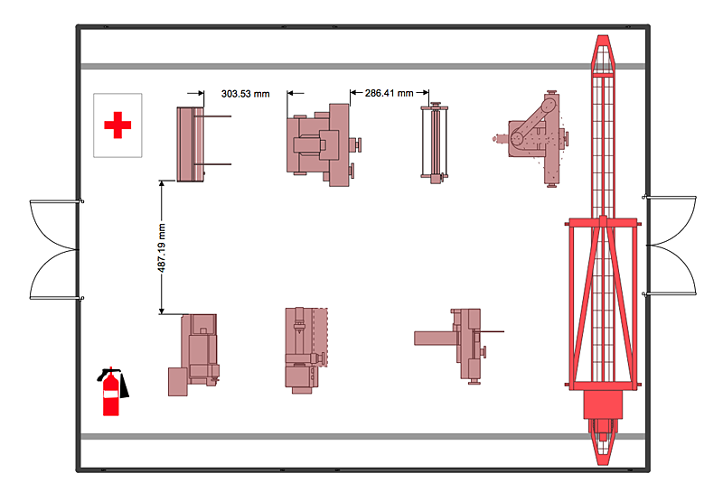
How to Create a Plant Layout Design
A plant construction process begins from a plant layout stage - an engineering stage used to design, analyze and finally choose the suitable configurations for a manufacturing plant. Plant Layout issues are core to any enterprise and are challenged in all types of manufacturing process. The sufficiency of layout influences the efficiency of subsequent operations. It is an important background for efficient manufacturing and also has a great deal with many questions. Once the place of the plant has been determined, the next important task before the management of the plant is to plan appropriate layout for the enterprise. Plant layout is used to create the most effective physical arrangement of machinery and equipment, with the plant building in such a manner so as to make quickest and cheapest way from a raw material to the shipment of the completed product Making a plan that shows the location of industrial equipment involves many different elements that can be managed using Con"A process flow diagram (PFD) is a diagram commonly used in chemical and process engineering to indicate the general flow of plant processes and equipment. The PFD displays the relationship between major equipment of a plant facility and does not show minor details such as piping details and designations. Another commonly used term for a PFD is a flowsheet. ...
Process flow diagrams of multiple process units within a large industrial plant will usually contain less detail and may be called block flow diagrams or schematic flow diagrams." [Process flow diagram. Wikipedia]
The process flow diagram (PFD) template for the ConceptDraw PRO diagramming and vector drawing software is included in the Chemical and Process Engineering solution from the Engineering area of ConceptDraw Solution Park.
- Annotated Diagram Of Planting Equipments
- Chemical Plant Equipment Symbols
- Crude oil distillation unit - PFD | Process flow diagram (PFD ...
- Diagrams Of Planting Machine
- Piping and Instrumentation Diagram Software | Plant Layout Plans ...
- How to Draw a Chemical Process Flow Diagram | Chemical and ...
- Diagrams Of Planting Machines
- Design elements - HVAC equipment | Plant Layout Plans | ATM UML ...
- Diagram Of Planting Machines
- Planting Machines Schematics Diagram
- Process Flowchart | Design elements - Industrial equipment ...
- Diagram Of Building Machines
- Process Flow Diagram
- Piping and instrumentation diagram template
- Process flow diagram (PFD) template
- Plant Layout Plans | CAD Drawing Software for Making Mechanic ...
- Plant Layout Plans | Interior Design Machines and Equipment ...
- How to Draw a Chemical Process Flow Diagram | Chemical and ...
- Plant Layout Plans | Factory layout floor plan | How to Create a Plant ...
- Gym Planning In Machine Lay Out

-template-process-flow-diagram-(pfd)-template.png--diagram-flowchart-example.png)