HelpDesk
How to Create a Residential Plumbing Plan
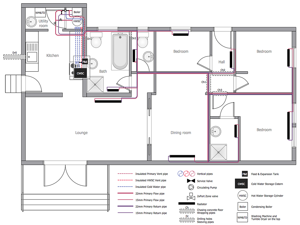
Planning a construction, or making a building plan you have take into account the plumbing and piping peculiarities. You need to make plan that shows the layout and connection of pipers, location of plumbing equipment, etc. Even with a plan changes may be necessary as you work, but a well-done plumbing and piping plan surely makes your work much easier. CnceptDraw Plumbing and Piping Plans solution provides you with the ability to create plumbing and piping plan that use official plumbing symbols. Making detailed Plumbing and Piping Plan will save time and costs. Also, drawing the Plumbing and Piping layout helps you considered through the project in detail, which may enable you to detect things that be probably missed. At least it certainly will minimize visits to the plumbing supply store and save your money. A clear, professional-looking Plumbing and Piping Plan also will make your communication with a building contractor more productive.UML Block Diagram
Use Case Diagram Taxi Service UML. This sample was created in ConceptDraw PRO diagramming and vector drawing software using the UML Use Case Diagram library of the Rapid UML Solution from the Software Development area of ConceptDraw Solution Park. This sample shows the work of the taxi service and is used by taxi stations, by airports, in the tourism field and delivery service.How to Draw a Landscape Design Plan
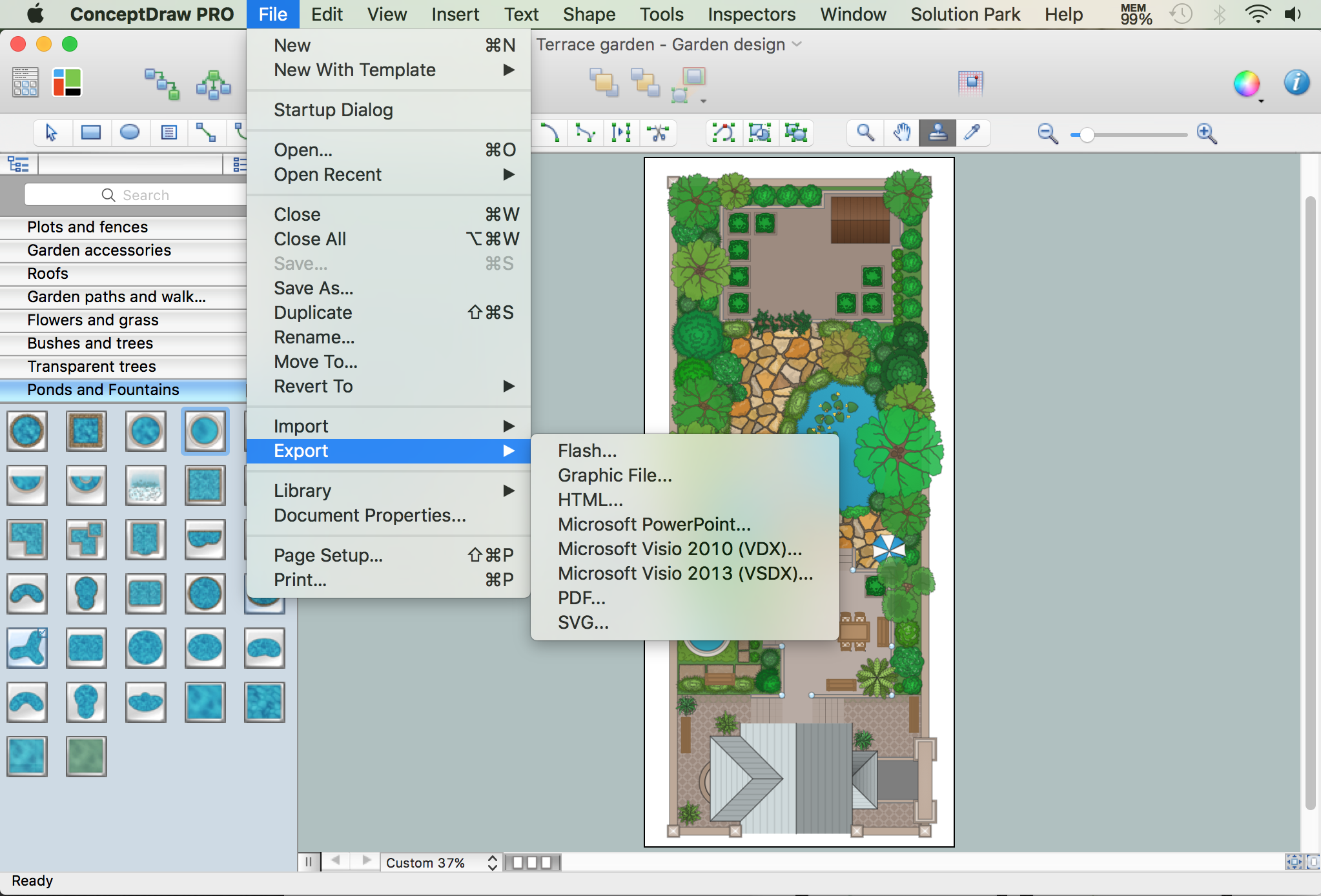
What is landscape design? It's a floor plan but for an outdoor area. Same as a floor plan, a landscape design represents visually any site using scaled dimensions. The main purpose of landscape design is to plan the layout for an outdoor area no matter is it a personal site plan for your home or a commercial plan for business. It may also be handful when a new installation, repair or even an outdoor event is planning. It helps to calculate time and decide which materials should be used in your project. Landscape designs perfectly gives the property owner and landscape contractor better vision for cost estimation, helping to ensure the project time and budget.Electrical Symbols — Electrical Circuits
A circuit diagram or wiring diagram uses symbols to represent parts of a circuit. Electrical and electronic circuits can be complicated. Making a drawing of the connections to all the component parts in the circuit's load makes it easier to understand how circuit components are connected. Drawings for electronic circuits are called "circuit diagrams". Drawings for electrical circuits are called "wiring diagrams". 26 libraries of the Electrical Engineering Solution of ConceptDraw PRO make your electrical diagramming simple, efficient, and effective. You can simply and quickly drop the ready-to-use objects from libraries into your document to create the electrical diagram.Diagramming Software for Design UML Component Diagrams
UML Component Diagram illustrate how components are wired together to larger components and software systems that shows the structure of arbitrarily complex systems. ConceptDraw Rapid UML solution delivers libraries contain pre-designed objects fit UML notation, and ready to draw professional UML Component Diagram.
Building Drawing Software for Design Machines and Equipment
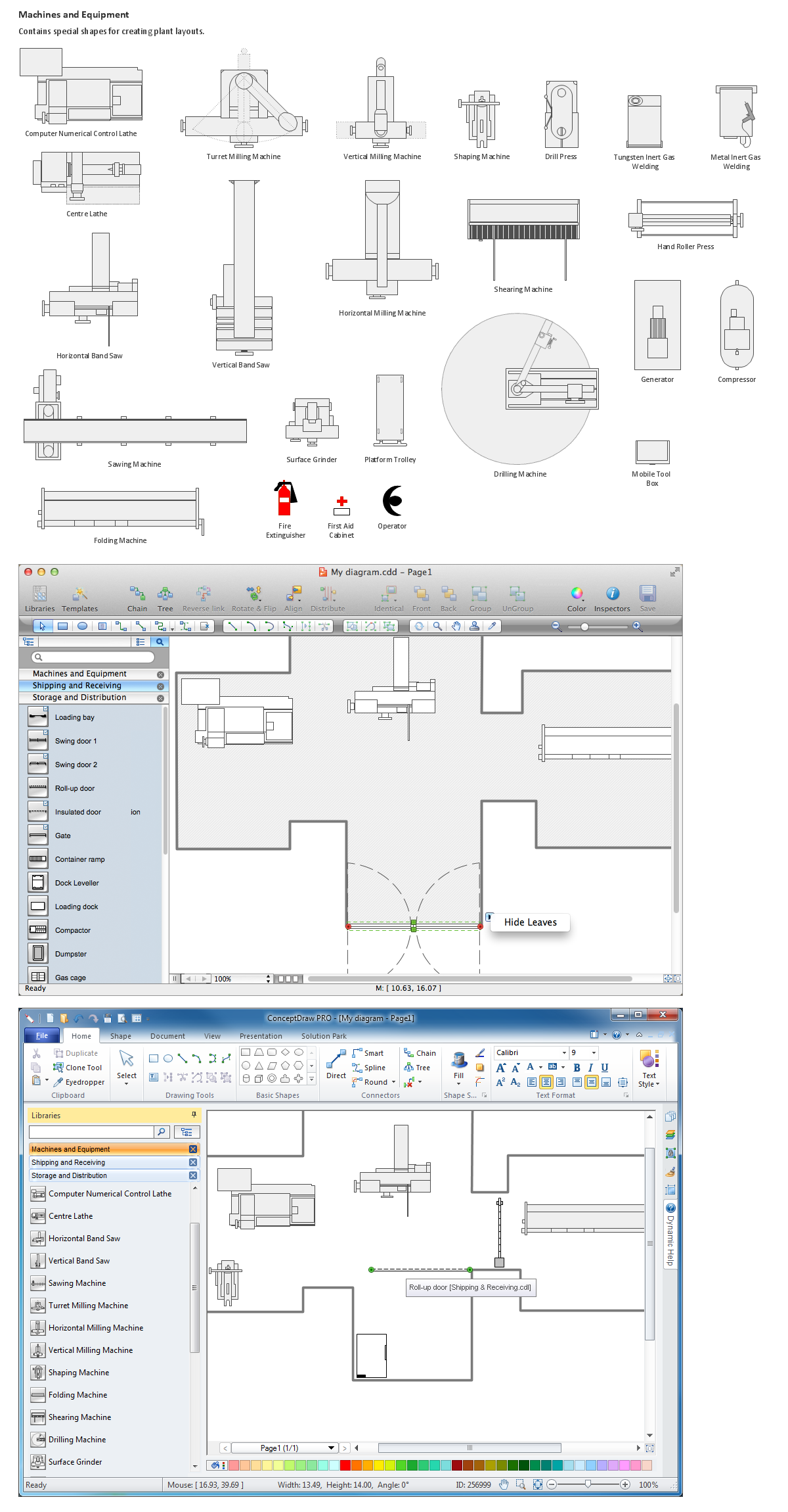
Use Building Drawing Tools to develop the plant layouts for production, storage, distribution, transport, shipping, and receiving of manufactured goods.
 Mechanical Engineering
This solution extends ConceptDraw PRO v.9 mechanical drawing software (or later) with samples of mechanical drawing symbols, templates and libraries of design elements, for help when drafting mechanical engineering drawings, or parts, assembly, pneumatic,
 Block Diagrams
Block diagrams solution extends ConceptDraw PRO software with templates, samples and libraries of vector stencils for drawing the block diagrams.
How To Create Restaurant Floor Plan in Minutes
Developing Floor Plans, Design Drawings, Plans of Furniture Placement for restaurants and cafes is one of the most responsible and important steps at their construction and designing. Selection of favorable design, the right style of furniture and decors largely determine the success and atmosphere of the institution. The restaurant floor planner ConceptDraw PRO is a perfect choice for architects and designers. Enhanced with Cafe and Restaurant Floor Plans solution it offers a lot of extensive vector symbol libraries and building plan elements for drawing Restaurant floor plans, Restaurant layouts, Restaurant furniture layouts, Cafe floor plans, Bar area floor plan, Fast food restaurant plan, etc. With ConceptDraw PRO you don't need to be an artist to create great-looking restaurant floor plan drawings in minutes, all needed drawing tools are delivered by Building Plans area solutions. Construct your own general plan of restaurant's premises, choose the furniture for your taste from the Cafe and Restaurant Floor Plans solution libraries and arrange it on the plan as you desire fast and easy. ConceptDraw PRO has many of the features found in Visio for Mac such as Drawing, Connection, Shape and Editing Tools.
Electrical Symbols, Electrical Diagram Symbols
When drawing Electrical Schematics, Electrical Circuit Diagrams, Power Systems Diagrams, Circuit and Wiring Diagrams, Digital and Analog Logic Schemes, you will obligatory need the electrical symbols and pictograms to represent various electrical and electronic devices, such as resistors, wires, transistors, inductors, batteries, switches, lamps, readouts, amplifiers, repeaters, relays, transmission paths, semiconductors, generators, and many more. Today these symbols are internationally standardized, so the diagrams designed using them are recognizable and comprehensible by specialists from different countries. Electrical Engineering Solution included to ConceptDraw Solution Park provides 26 libraries with 926 commonly used electrical schematic and electrical engineering symbols making the reality the easy drawing of Electrical diagrams, schematics and blueprints. Now you need only a few minutes to create great-looking Electrical diagram, simply choose required electrical design elements from the libraries, drag them on the needed places at the document and connect in a suitable way.Software development with ConceptDraw Products
Internet solutions on ConceptDraw base. What may interest developers of Internet solutions.
 Note Exchange
This solution extends ConceptDraw MINDMAP software with the ability to exchange with Evernote, and access mind maps anywhere, on any computer or mobile device via Evernote.
IDEF9 Standard
Use Case Diagrams technology. An effective management of changes is significantly facilitated by way of definition and documenting of business-requirements.
 Language Learning
Language Learning solution extends ConceptDraw PRO software with templates, samples and library of vector stencils for drawing the sentence diagrams.
- Parts Of A Plumbing And Piping Plans
- Building Drawings Parts Technical Drawing
- Pipe Tools And Parts With Drawing Symbol
- Line Graphs | Plumbing and Piping Plans | Process Flowchart | Line ...
- Value stream map parts | Plumbing and Piping Plans | Plant Layout ...
- Plumbing and Piping Plans | How to Create a Residential Plumbing ...
- Technical drawing - Machine parts assembling | Interior Design ...
- Technical drawing - Machine parts assembling | Mechanical ...
- Building Drawing Design Element: Plumbing | Piping and ...
- Building Drawing Software for Designing Plumbing | Mechanical ...
- Building Drawing Software for Designing Plumbing
- Mechanical Engineering | Building Drawing Software for Designing ...
- Plumbing and Piping Plans | ConceptDraw Solution Park | Piping ...
- Technical drawing - Machine parts assembling | Process Flowchart ...
- Technical Drawing Software | Mechanical Engineering | Building ...
- Interior Design Piping Plan - Design Elements | Piping and ...
- Technical Drawing Software
- Plumbing and Piping Plans | Mechanical Engineering | Interior ...
- ConceptDraw Solution Park | Nature | Plumbing and Piping Plans ...
- Residential Plumbing Plan Drawings


