The vector stencils library "Pneumatic pumps and motors" contains 39 symbols of pneumatic pumps, motors and pump-motors for designing the engineering drawings of pneumatic circuits.
"A pneumatic motor or compressed air engine is a type of motor which does mechanical work by expanding compressed air. Pneumatic motors generally convert the compressed air energy to mechanical work through either linear or rotary motion. Linear motion can come from either a diaphragm or piston actuator, while rotary motion is supplied by either a vane type air motor or piston air motor." [Pneumatic motor. Wikipedia]
"A gas compressor is a mechanical device that increases the pressure of a gas by reducing its volume. An air compressor is a specific type of gas compressor.
Compressors are similar to pumps: both increase the pressure on a fluid and both can transport the fluid through a pipe. As gases are compressible, the compressor also reduces the volume of a gas. Liquids are relatively incompressible; while some can be compressed, the main action of a pump is to pressurize and transport liquids." [Gas compressor. Wikipedia]
The shapes example "Design elements - Pneumatic pumps and motors" was created using the ConceptDraw PRO diagramming and vector drawing software extended with the Mechanical Engineering solution from the Engineering area of ConceptDraw Solution Park.
Pneumatic pump and motor symbols

The vector stencils library "Pneumatic pumps and motors" contains 39 symbols of pneumatic pumps, motors and pump-motors.
Use these shapes for designing the engineering drawings of pneumatic circuits in the ConceptDraw PRO diagramming and vector drawing software extended with the Mechanical Engineering solution from the Engineering area of ConceptDraw Solution Park.
www.conceptdraw.com/ solution-park/ engineering-mechanical
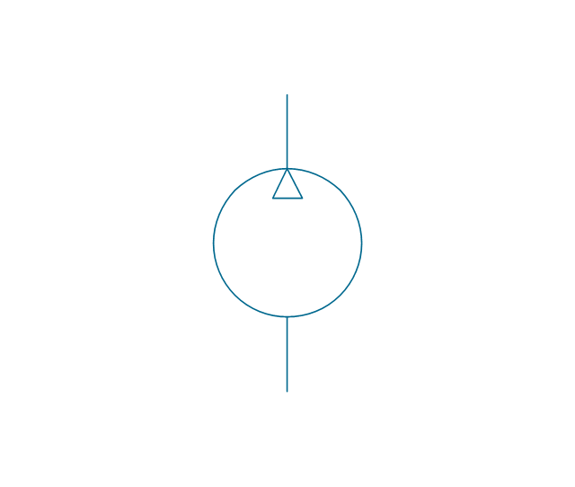
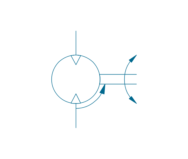
Pump, pneumatic
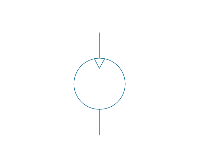
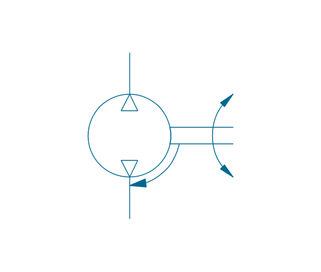
Motor, pneumatic
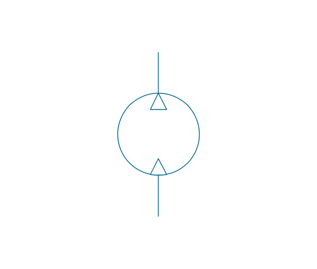
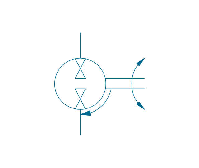
Pump-motor, pneumatic
Pump, fixed, external drain
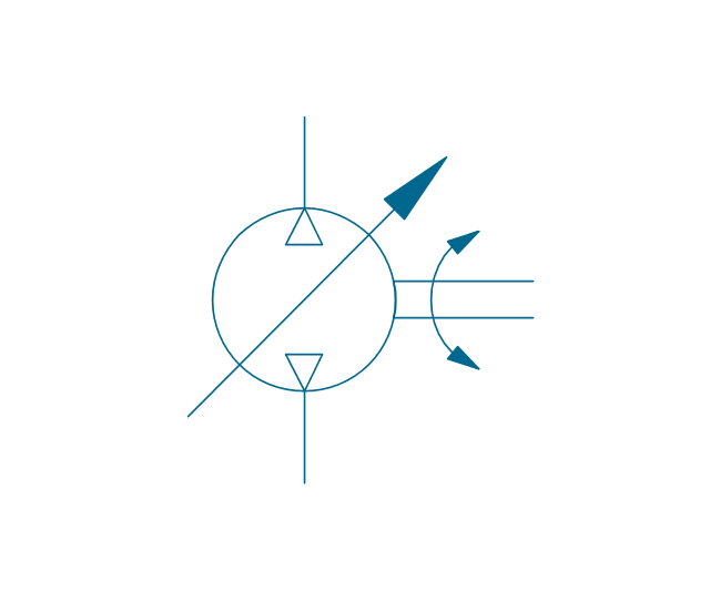
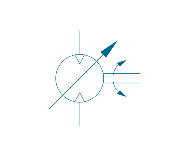
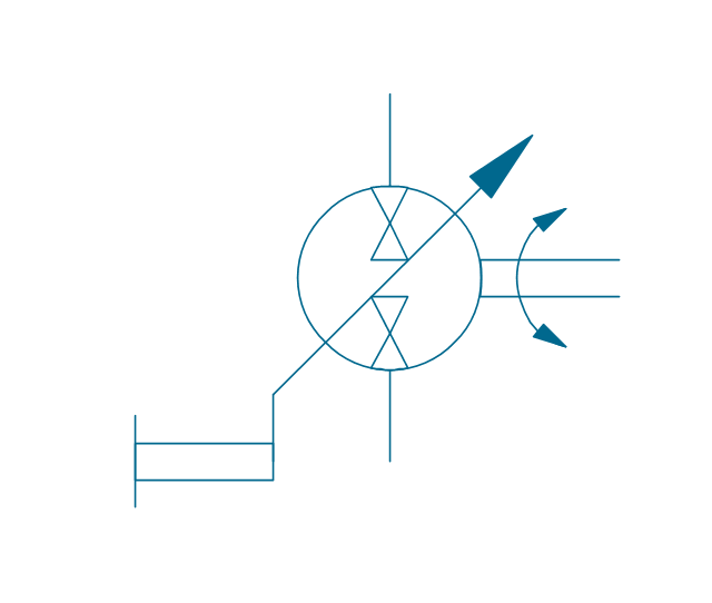
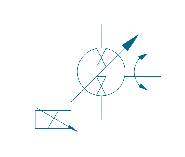
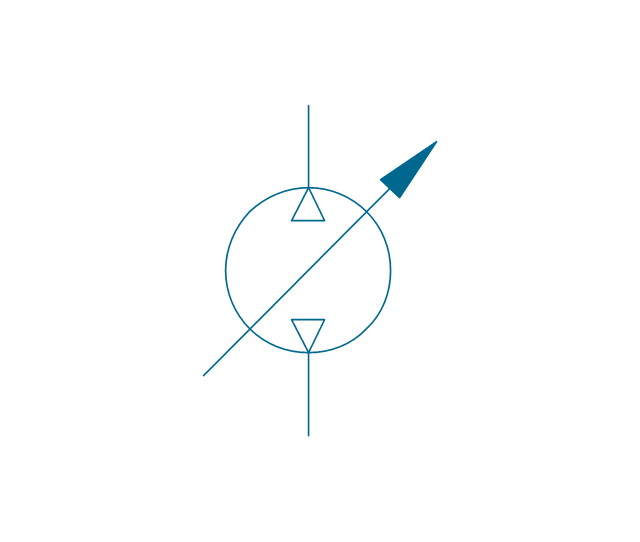
Pump, variable
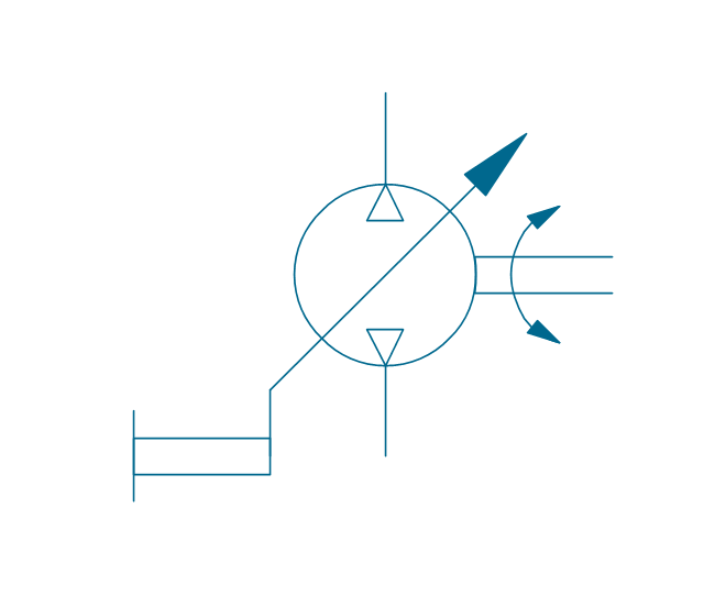
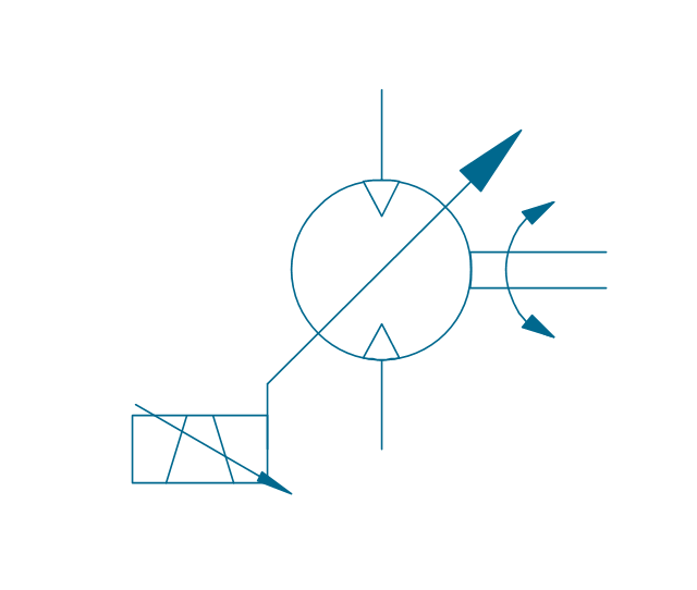
Pump, var., manual override
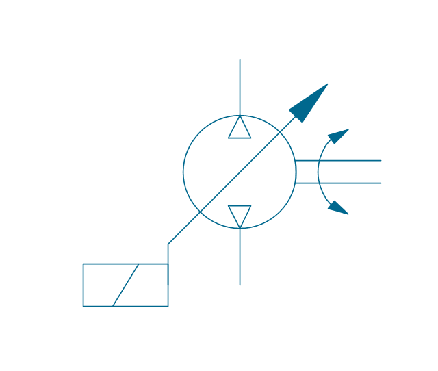
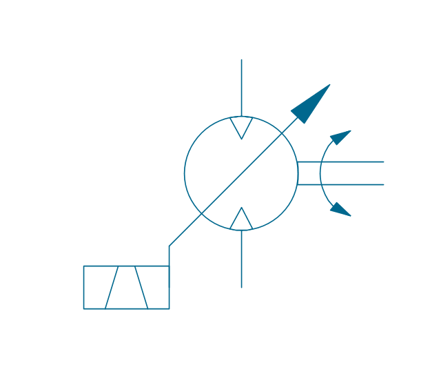
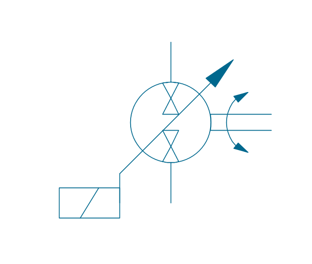
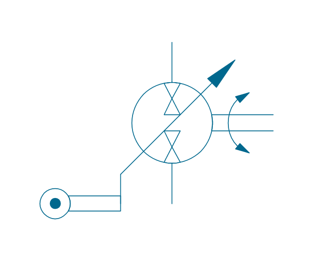
Pump, var., solenoid
Pump, var., solenoid 2

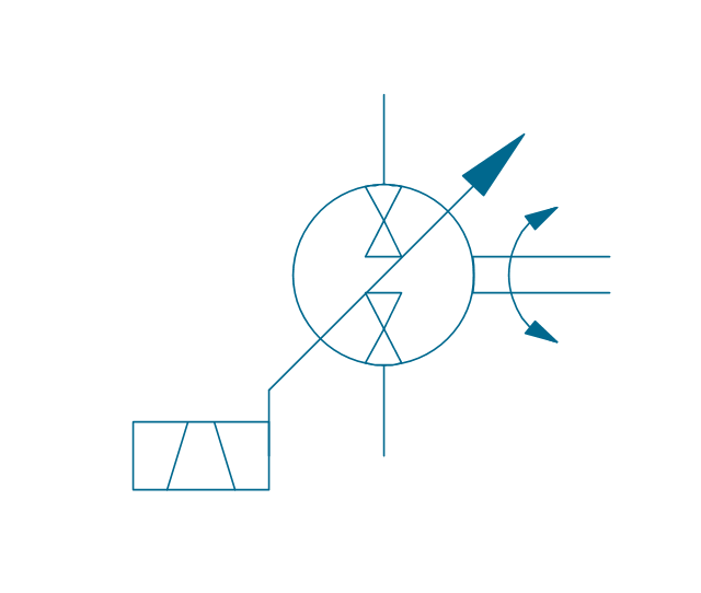
Pump, var., var. solenoid

Pump, var., var. solenoid 2

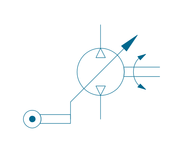
Pump, var., var., roller
Motor, fixed, external drain
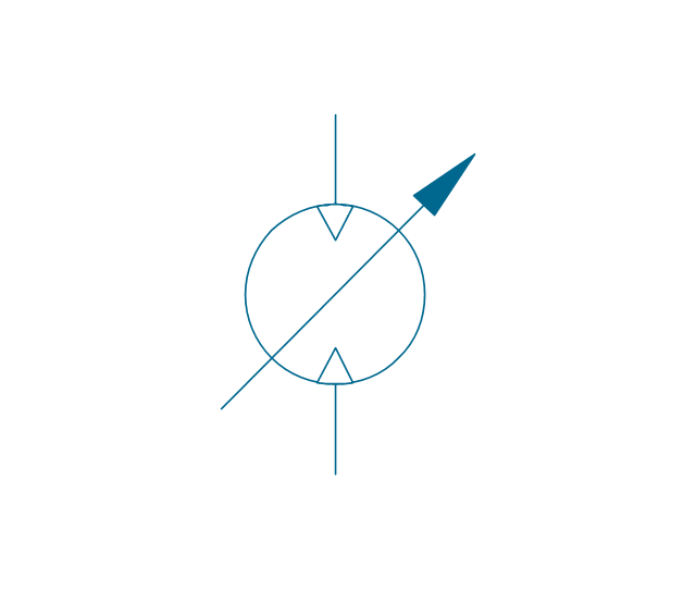
Motor, variable
Motor, var., manual override

Motor, var., solenoid

Motor, var., solenoid 2
Motor, var., var. solenoid

Motor, var., var. solenoid 2
Motor, var., var., roller

Pump-motor, fixed, external drain
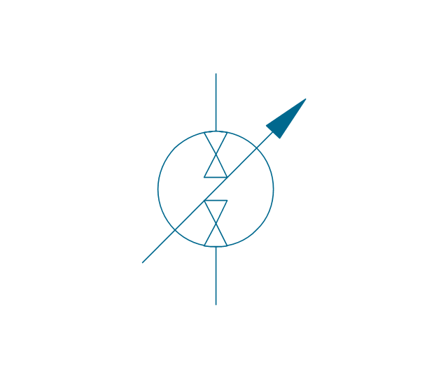
Pump-motor, variable

Pump-motor, var., manual override
Pump-motor, var., solenoid
Pump-motor, var., solenoid 2
Pump-motor, var., var. solenoid
Pump-motor, var., var. solenoid 2

Pump-motor, var., var., roller
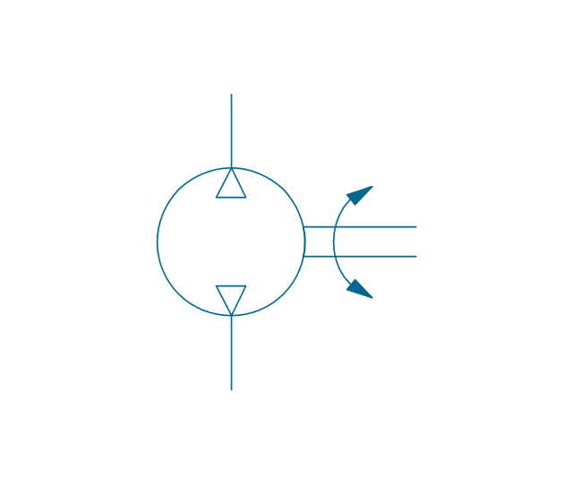
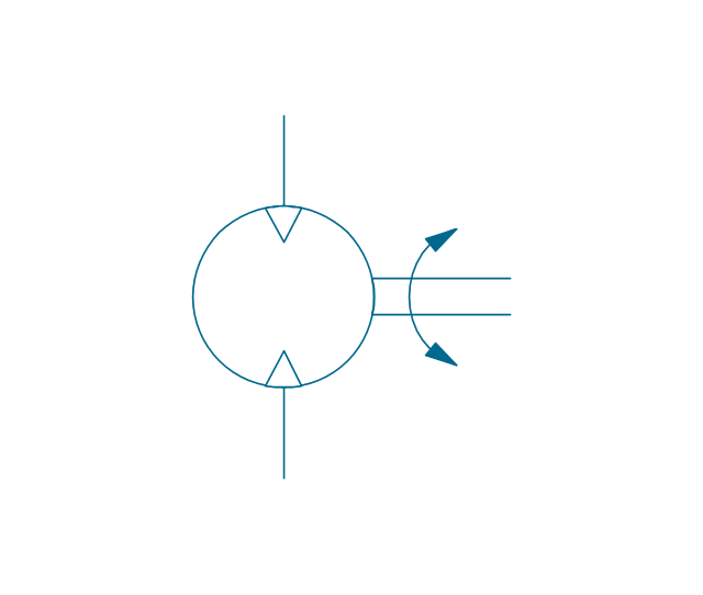
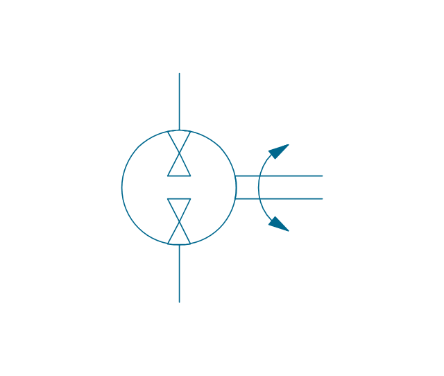
Pump, variable (sgl side)
-pneumatic-pumps-and-motors---vector-stencils-library.png--diagram-flowchart-example.png)
Pump, variable (dbl side)
-pneumatic-pumps-and-motors---vector-stencils-library.png--diagram-flowchart-example.png)
Pump, fixed 2
Motor, fixed 2
Motor, variable (sgl side)
-pneumatic-pumps-and-motors---vector-stencils-library.png--diagram-flowchart-example.png)
Motor, variable (dbl side)
-pneumatic-pumps-and-motors---vector-stencils-library.png--diagram-flowchart-example.png)
Pump-motor, fixed 2
Pump-motor, variable (sgl side)
-pneumatic-pumps-and-motors---vector-stencils-library.png--diagram-flowchart-example.png)
Pump-motor, variable (dbl side)
-pneumatic-pumps-and-motors---vector-stencils-library.png--diagram-flowchart-example.png)
Pump, variable displacement
Motor, variable displacement
Pump-motor, variable displacement
Mechanical Drawing Symbols

The vector stencils library "Fluid power equipment" contains 113 symbols of hydraulic and pneumatic equipment including pumps, motors, air compressors, cylinders, meters, gauges, and actuators.
Use it to design fluid power and hydraulic control systems in the ConceptDraw PRO diagramming and vector drawing software extended with the Mechanical Engineering solution from the Engineering area of ConceptDraw Solution Park.
www.conceptdraw.com/ solution-park/ engineering-mechanical
Use it to design fluid power and hydraulic control systems in the ConceptDraw PRO diagramming and vector drawing software extended with the Mechanical Engineering solution from the Engineering area of ConceptDraw Solution Park.
www.conceptdraw.com/ solution-park/ engineering-mechanical
Actuator (semi-rotary), pneumatic
,-pneumatic-fluid-power-equipment---vector-stencils-library.png--diagram-flowchart-example.png)
Actuator (semi-rotary), hydraulic
,-hydraulic-fluid-power-equipment---vector-stencils-library.png--diagram-flowchart-example.png)
Drive unit, pneumatic

Drive unit, hydraulic

Sgl-act. cylinder, pneum., left spring

Sgl-act. cylinder, pneum., right spring

Sgl-act. cylinder, pneumatic

Sgl-act. cylinder, hydr., left spring

Sgl-act. cylinder, hydr., right spring

Sgl-act. cylinder, hydraulic

Dbl-act. cylinder, pneumatic

Dbl-act. cylinder, pneum., sgl cushion

Dbl-act. cylinder, pneum., dbl cushion

Dbl-act. cylinder, pneum., adjustable

Dbl-act. cylinder, pneum., sgl cushion, adj.

Dbl-act. cylinder, pneum., dbl cushion, adj.

Dbl-act. cylinder, hydraulic

Dbl-act. cylinder, hydr., sgl cushion

Dbl-act. cylinder, hydr., dbl cushion

Dbl-act. cylinder, hydr., adjustable

Dbl-act. cylinder, hydr., sgl cushion, adj.

Dbl-act. cylinder, hydr., dbl cushion, adj.

Dbl-act. cylinder, magnetic

Dbl-act. cylinder, magn., sgl cushion

Dbl-act. cylinder, magn., dbl cushion

Dbl-act. cylinder, magn., adjustable

Dbl-act. cylinder, magn., sgl cushion, adj.

Dbl-act. cylinder, magn., dbl cushion, adj.

Dbl-act. dbl-end. cylinder, pneumatic

Dbl-act. dbl-end. cylinder, pneum., sgl cushion

Dbl-act. dbl-end. cylinder, pneum., dbl cushion

Dbl-act. dbl-end. cylinder, pneum., adjustable

Dbl-act. dbl-end. cylinder, pneum., sgl cushion, adj.

Dbl-act. dbl-end. cylinder, pneum., dbl cushion, adj.

Dbl-act. dbl-end. cylinder, hydraulic

Dbl-act. dbl-end. cylinder, hydr., sgl cushion

Dbl-act. dbl-end. cylinder, hydr., dbl cushion

Dbl-act. dbl-end. cylinder, hydr., adjustable

Dbl-act. dbl-end. cylinder, hydr., sgl cushion, adj.

Dbl-act. dbl-end. cylinder, hydr., dbl cushion, adj.

Telescopic cylinder, pneum., dbl-act.

Telescopic cylinder, hydr., dbl-act.

Telescopic cylinder, pneum., sgl-act.

Telescopic cylinder, hydr., sgl-act.

Actuator, hydraulic-pneumatic

Actuator, pneumatic-hydraulic

Intensifier, pneumatic

Intensifier, hydraulic

Intensifier, hydraulic-pneumatic

Intensifier, pneumatic-hydraulic

Intensifier, pneumatic-hydraulic

Intensifier, hydraulic-pneumatic

Actuator, pneumatic-hydraulic

Actuator, hydraulic-pneumatic

Accumulator

Accumulator, gas loaded

Accumulator, spring loaded

Accumulator, auxiliary gas bottle

Air receiver

Energy source, pneumatic

Energy source, hydraulic

Energy source, electric motor

Energy source, non-electric prime mover

Vented reservoir

Sealed reservoir

Filter

Filter, magnetic element

Filter, contamination indicator

Automatic drain filter separator

Manual drain filter separator

Separator, automatic drain

Separator, manual drain

Air dryer

Lubricator

Air service unit, filter, separator

Air service unit, separator

Air service unit, filter

Air service unit

Liquid cooler

Gas cooler

Cooler

Liquid heater

Gas heater

Heater

Liquid temperature controller

Gas temperature controller

Temperature controller

Liquid temperature controller 2

Gas temperature controller 2

Temperature controller 2

Pressure indicator

Pressure gauge

Differential pressure gauge

Thermometer

Liquid level measuring instrument

Flow indicator

Flow meter

Integrating flow meter

Tachometer

Torque measurement equipment

Pressure switch

Limit switch

Transducer

Pulse counter

Pulse counter 2

Silencer

Drain (inlet below fluid, drain line)
-fluid-power-equipment---vector-stencils-library.png--diagram-flowchart-example.png)
Drain (inlet below fluid, return line)
-fluid-power-equipment---vector-stencils-library.png--diagram-flowchart-example.png)
Drain (inlet above fluid, drain line)
-fluid-power-equipment---vector-stencils-library.png--diagram-flowchart-example.png)
Drain (inlet above fluid, return line)
-fluid-power-equipment---vector-stencils-library.png--diagram-flowchart-example.png)
Oil tank

Oil tank, empty

Air compressor

This example engineering drawing showing the hydraulic directional control valve usage with floating motor and pressure compensated pump is redesigned using the ConceptDraw PRO diagramming and vector drawing software from the Wikimedia Commons file: DCV 17.jpg.
[commons.wikimedia.org/ wiki/ File:DCV_ 17.jpg]
This file is licensed under the Creative Commons Attribution-Share Alike 3.0 Unported license.
[creativecommons.org/ licenses/ by-sa/ 3.0/ deed.en]
"Directional control valves are one of the most fundamental parts in hydraulic machinery as well and pneumatic machinery. They allow fluid flow into different paths from one or more sources. They usually consist of a spool inside a cylinder which is mechanically or electrically controlled. The movement of the spool restricts or permits the flow, thus it controls the fluid flow. ...
The spool (sliding type) consists of lands and grooves.The lands block oil flow through the valve body. The grooves allow oil or gas to flow around the spool and through the valve body. There are two fundamental positions of directional control valve namely normal position where valve returns on removal of actuating force and other is working position which is position of a valve when actuating force is applied. There is another class of valves with 3 or more position that can be spring centered with 2 working position and a normal position. ...
Directional control valves can be classified according to:
(1) number of ports;
(2) number of positions;
(3) actuating methods;
(4) type of spool." [Directional control valve. Wikipedia]
The fluid power equipment drawing example "Directional control valve" is included in the Mechanical Engineering solution from the Engineering area of ConceptDraw Solution Park.
Hydraulic equipment schematic

"Directional control valves are one of the most fundamental parts in hydraulic machinery as well and pneumatic machinery. They allow fluid flow into different paths from one or more sources. They usually consist of a spool inside a cylinder which is mechanically or electrically controlled. The movement of the spool restricts or permits the flow, thus it controls the fluid flow." [Directional control valve. Wikipedia]
This example engineering drawing showing the directional control valve usage with fixed volume pump and hydraulic cylinder is redesigned using the ConceptDraw PRO diagramming and vector drawing software from Wikimedia Commons file: DCV 19.jpg.
[commons.wikimedia.org/ wiki/ File:DCV_ 19.jpg]
This file is licensed under the Creative Commons Attribution-Share Alike 3.0 Unported license.
[creativecommons.org/ licenses/ by-sa/ 3.0/ deed.en]
The fluid power equipment drawing example "Directional control valve" is included in the Mechanical Engineering solution from the Engineering area of ConceptDraw Solution Park.
Hydraulic equipment schematic

- Design elements - Pneumatic pumps and motors | Design elements ...
- Design elements - Pneumatic pumps and motors | Pneumatic pumps ...
- Design elements - Pneumatic pumps and motors
- Design elements - Hydraulic pumps and motors | Design elements ...
- Mechanical Drawing Symbols | Design elements - Pneumatic pumps ...
- Pneumatic pumps and motors - Vector stencils library | Design ...
- Mechanical Drawing Symbols | Design elements - Fluid power ...
- Design elements - Hydraulic pumps and motors | Pneumatic pumps ...
- Pneumatic 5-ported 3-position valve template - Mac | Design ...
- Engineering Drawing Design Symbols
- Mechanical Drawing Symbols | Design elements - Hydraulic pumps ...
- Design elements - Pneumatic pumps and motors | Interior Design ...
- Design elements - Pneumatic pumps and motors | Pumps - Vector ...
- Pneumatic pumps and motors
- Mechanical Drawing Symbols | Pneumatic 5-ported 3-position valve ...
- Mechanical Drawing Symbols | Design elements - Valve assembly ...
- Pneumatic pumps and motors - Vector stencils library | Ventilation ...
- Design elements - Terminals and connectors | Design elements ...
- Mechanical Engineering Design Symbols
- Mechanical Engg Design Symbols