The vector stencils library "MS Windows Vista user interface" contains 76 MS Windows Vista design elements.
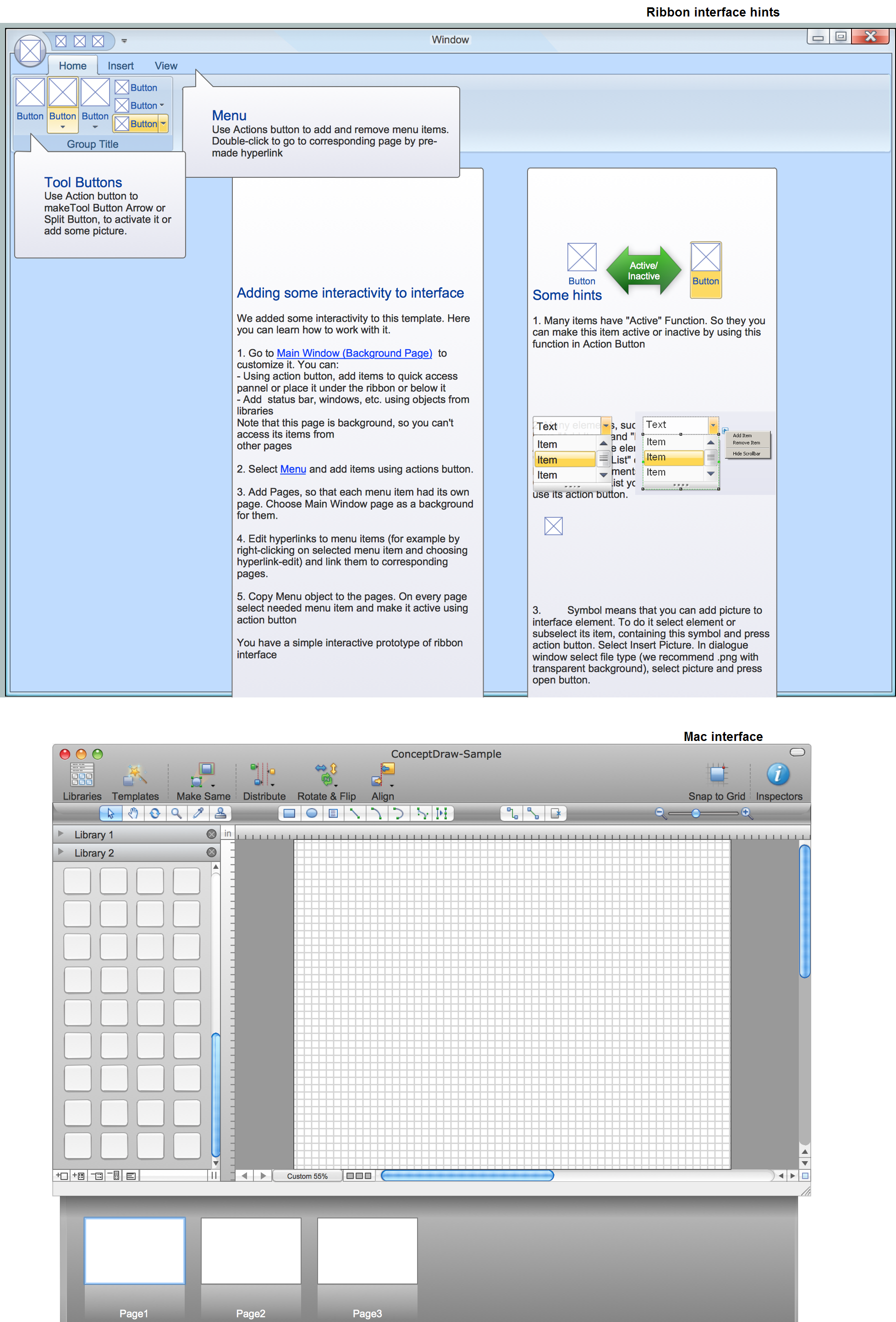
Use it for designing Microsoft ribbon graphic user interface (GUI) of software for computers with MS Windows Vista OS in the ConceptDraw PRO diagramming and vector drawing software extended with the Graphic User Interface solution from the Software Development area of ConceptDraw Solution Park.
Use it for designing Microsoft ribbon graphic user interface (GUI) of software for computers with MS Windows Vista OS in the ConceptDraw PRO diagramming and vector drawing software extended with the Graphic User Interface solution from the Software Development area of ConceptDraw Solution Park.
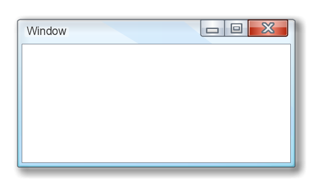
Window
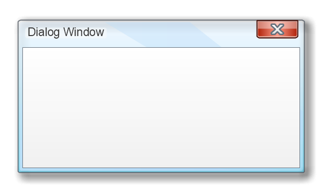
Dialog Window
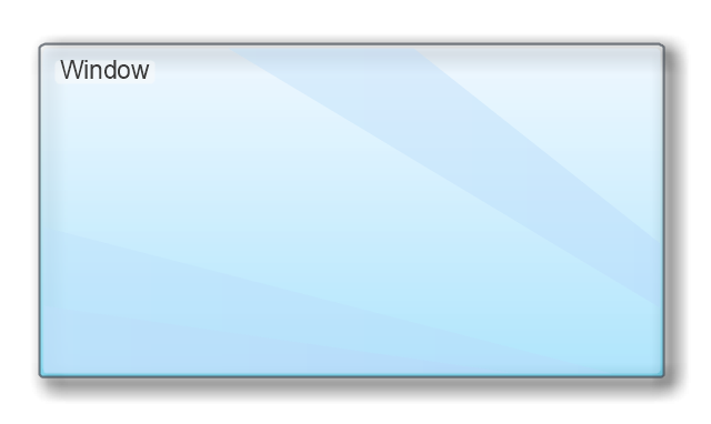
Empty Window
Field

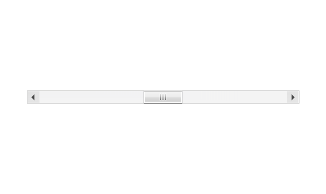
Horizontal Scrollbar
Vertical Scrollbar
Window Buttons
Window Buttons
Window Button 1

Window Button 2

Window Button 3

Window Button 4

Navigation

Menu Bar
Gradient Menu Bar
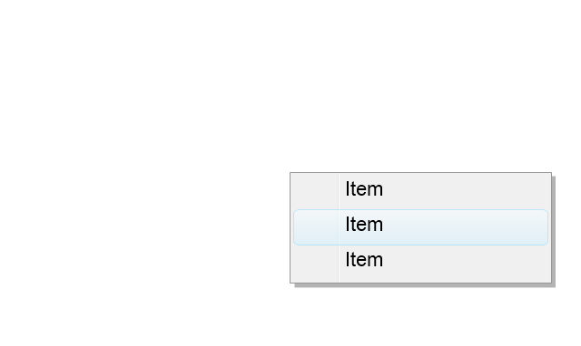
Drop-down Menu
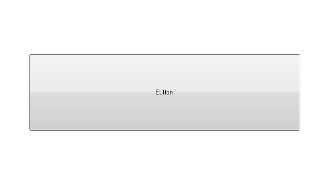
Button
Toolbar Pannel

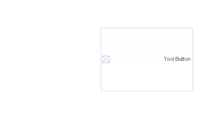
Tool Button
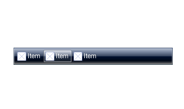
Primary Toolbar

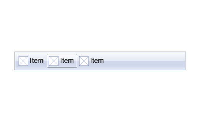
Toolbar 1
Toolbar 2
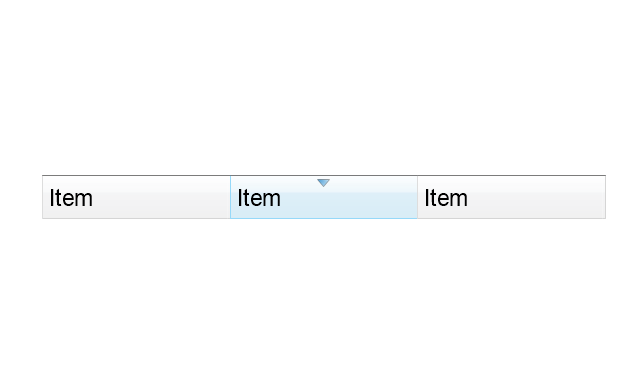
Customizable Tollbar

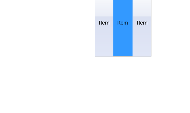
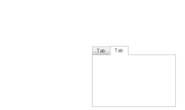
Tab View
List View
Text Field
Vertical Separator

Horizontal Separator

Group Box
Text Label

Link

Line Edit
Search

Search with Button

Spin Box
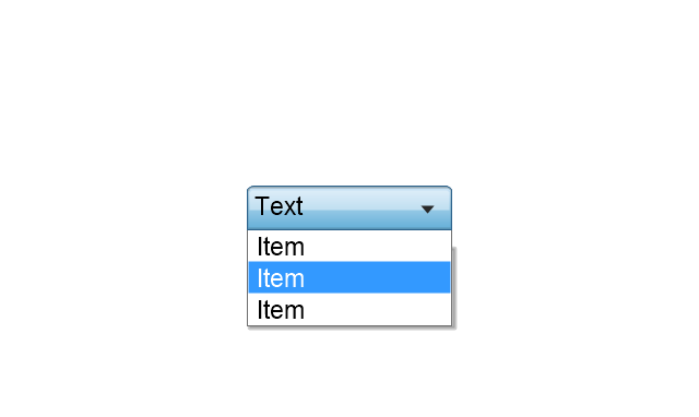
Combo-box
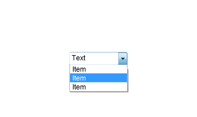
Editable Combo-box
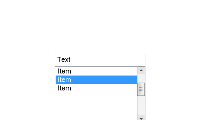
Editable List Box
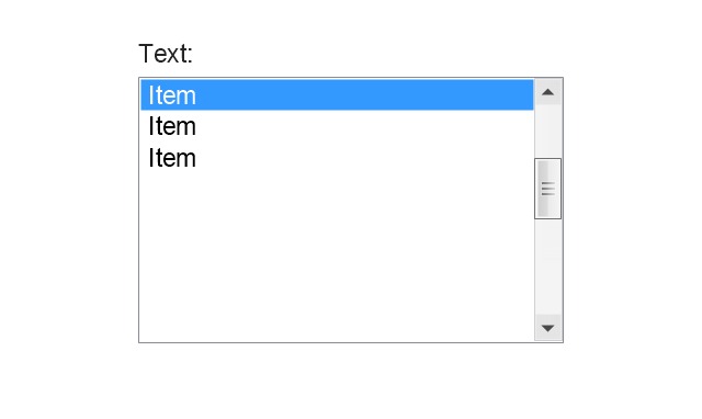
List Box
Single-selection List
Multiple-selection List
Check Box

Radio Button

Check box group
Radio Buttons Group
Progress Bar

Modal Progress Bar

Vertical Slider with Ticks
Horizontal Slider with Ticks
Dial

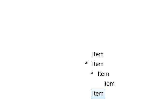
Catalogue Tree
Tree View 1
Tree View 2
Vertical Spacer

Horizontal Spacer

Chevron 1
Arrow 1
Arrow 2
Plus/Minus Control

Rotating Triangle

Chevron 3
Chevron 2
Normal Select Cursor

Link Select Cursor

Text Select Cursor

Working in Background Pointer

Busy Pointer

Unavailable Cursor

Precision Select Cursor

Error Icon
Warning Icon
Information Icon
Question Mark Icon
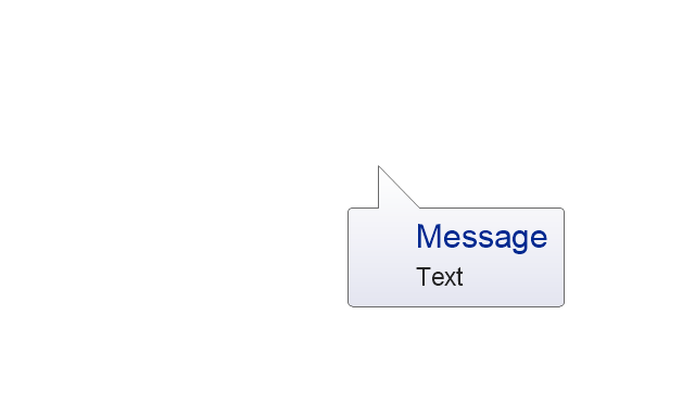
Balloon
Tooltip/Infotip

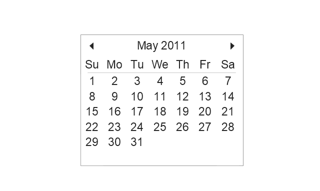
Calendar
The vector stencils library "MS Windows Vista user interface" contains 76 MS Windows Vista design elements.
Use it for designing Microsoft ribbon graphic user interface (GUI) of software for computers with MS Windows Vista OS in the ConceptDraw PRO diagramming and vector drawing software extended with the Graphic User Interface solution from the Software Development area of ConceptDraw Solution Park.
Use it for designing Microsoft ribbon graphic user interface (GUI) of software for computers with MS Windows Vista OS in the ConceptDraw PRO diagramming and vector drawing software extended with the Graphic User Interface solution from the Software Development area of ConceptDraw Solution Park.
Window
Dialog Window
Empty Window
Field
Horizontal Scrollbar
Vertical Scrollbar
Window Buttons
Window Buttons
Window Button 1
Window Button 2
Window Button 3
Window Button 4
Navigation
Menu Bar
Gradient Menu Bar
Drop-down Menu
Button
Toolbar Pannel
Tool Button
Primary Toolbar
Toolbar 1
Toolbar 2
Customizable Tollbar
Tab View
List View
Text Field
Vertical Separator
Horizontal Separator
Group Box
Text Label
Link
Line Edit
Search
Search with Button
Spin Box
Combo-box
Editable Combo-box
Editable List Box
List Box
Single-selection List
Multiple-selection List
Check Box
Radio Button
Check box group
Radio Buttons Group
Progress Bar
Modal Progress Bar
Vertical Slider with Ticks
Horizontal Slider with Ticks
Dial
Catalogue Tree
Tree View 1
Tree View 2
Vertical Spacer
Horizontal Spacer
Chevron 1
Arrow 1
Arrow 2
Plus/Minus Control
Rotating Triangle
Chevron 3
Chevron 2
Normal Select Cursor
Link Select Cursor
Text Select Cursor
Working in Background Pointer
Busy Pointer
Unavailable Cursor
Precision Select Cursor
Error Icon
Warning Icon
Information Icon
Question Mark Icon
Balloon
Tooltip/Infotip
Calendar
HelpDesk
How to Connect an Image to a Topic in Your Mind Map

UML Class Diagram Constructor

GUI Prototyping with ConceptDraw DIAGRAM
HelpDesk
How to Work with Multipage Mind Maps

HelpDesk
How to Create a CCTV Diagram

UML Notation

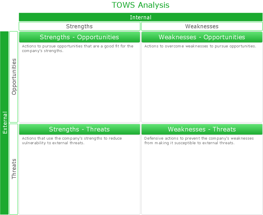
SWOT Analysis Solution - Strategy Tools
Databases Access Objects Model with ConceptDraw DIAGRAM

UML Class Diagram. Design Elements

Create Floor Plans Easily with ConceptDraw DIAGRAM


UML Class Diagram Generalization Example UML Diagrams

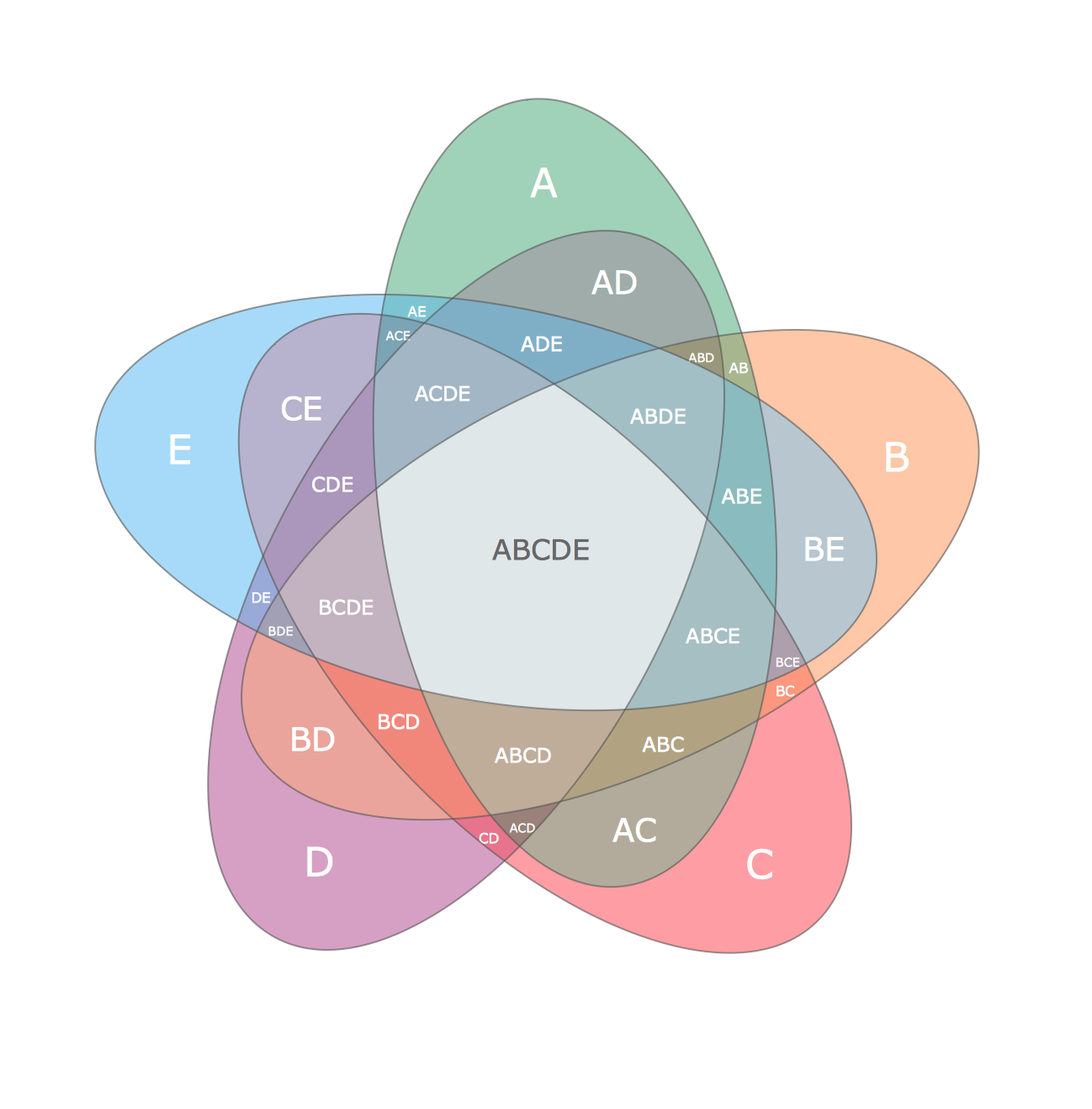
Multi Layer Venn Diagram. Venn Diagram Example
HelpDesk
How to Create a Mind Map with Multiple Main Ideas

- Dropdown Icon Png
- Vertical White Line Transparent Png
- Ribbon Design Png
- Horizontal Vector Png
- Ribbon Vector Png
- Rotating Arrows Png
- Ribbons Vector Png
- Line Separator Png
- IDEF0 diagram - Inter-box connections | VoIP call with SIM box and ...
- Drop Vector Png
- Buttons Icons Png
- Mac OS X Lion user interface - Vector stencils library | Ribbon ...
- Laboratory equipment - Vector stencils library | Gas Burner Icon Png
- MS Windows Vista user interface - Vector stencils library | MS ...
- Active Directory Diagram | MS Windows Vista user interface - Vector ...
- Business diagrams & Org Charts with ConceptDraw PRO | How to ...
- Mail Vector Png
- Windows 8 User Interface | Windows Vista graphic user interface ...
- MS Windows Vista user interface - Vector stencils library | Windows ...
- MS Windows Vista user interface - Vector stencils library