This interactive voice response (IVR) diagram sample shows the Scheme of VoIP call with SIM box and gateway. It was designed on the base of the Wikimedia Commons file: Scheme of VoIP call with Sim box.png. [commons.wikimedia.org/ wiki/ File:Scheme_ of_ VoIP_ call_ with_ Sim_ box.png]
This file is licensed under the Creative Commons Attribution-Share Alike 4.0 International license. [creativecommons.org/ licenses/ by-sa/ 4.0/ deed.en]
"A SIM box (also called a SIM bank) is device used as part of a VoIP gateway installation. It contains a number of SIM cards, which are linked to the gateway but housed and stored separately from it. A SIM box can have SIM cards of different mobile operators installed, permitting it to operate with several GSM gateways located in different places." [SIM box. Wikipedia]
The IVR diagram example "VoIP call with SIM box and gateway" was designed using ConceptDraw PRO diagramming and vector drawing software extended with the Interactive Voice Response Diagrams solution from the Computer and Networks area of ConceptDraw Solution Park.
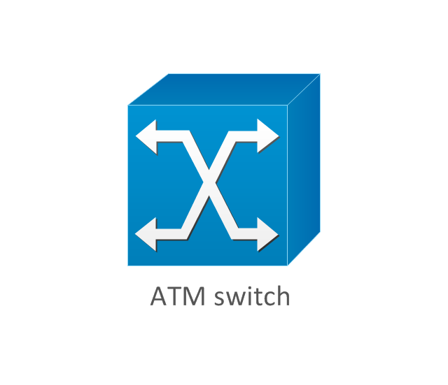
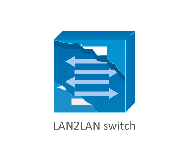
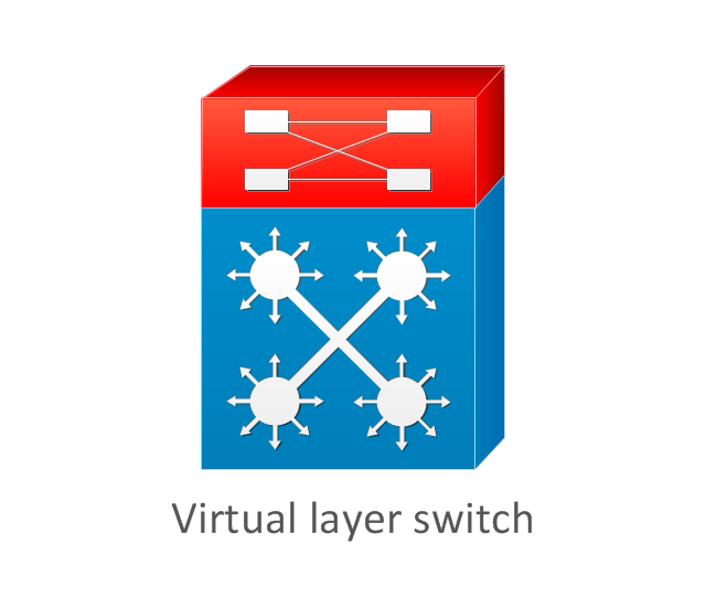
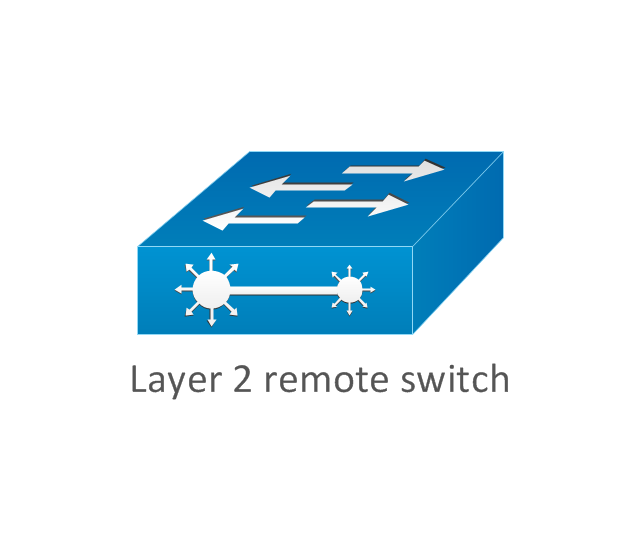
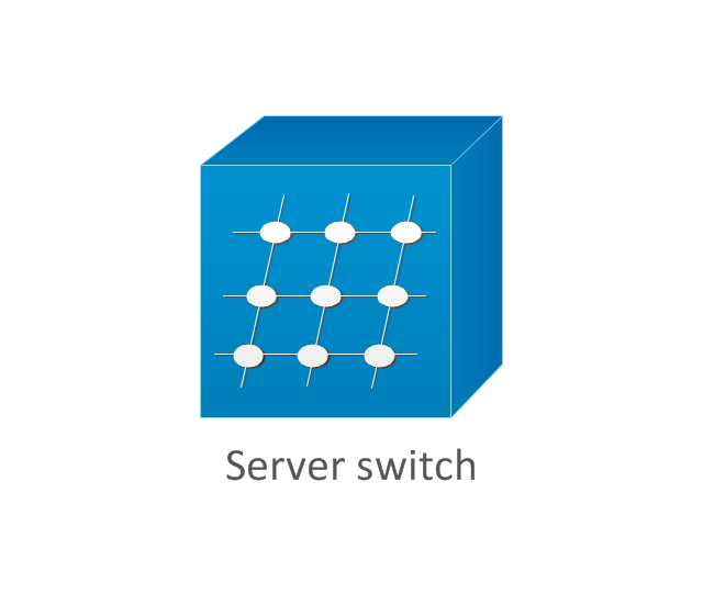
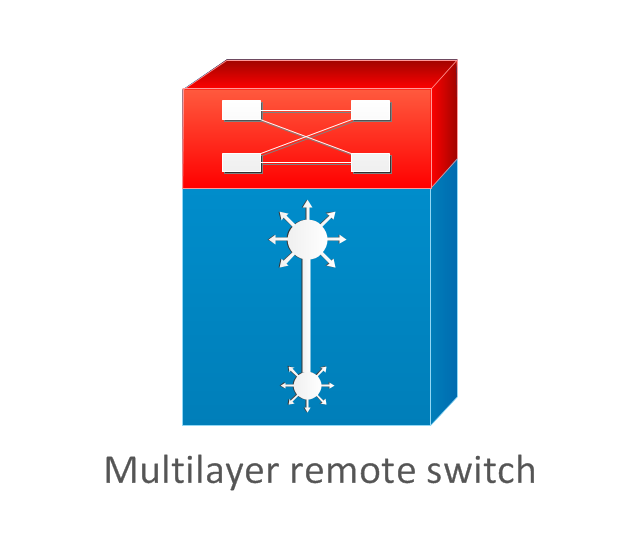
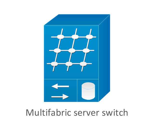
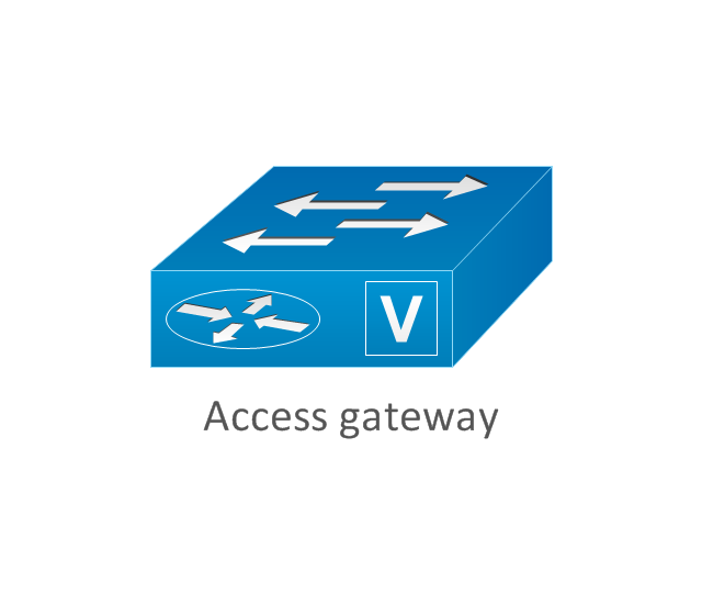
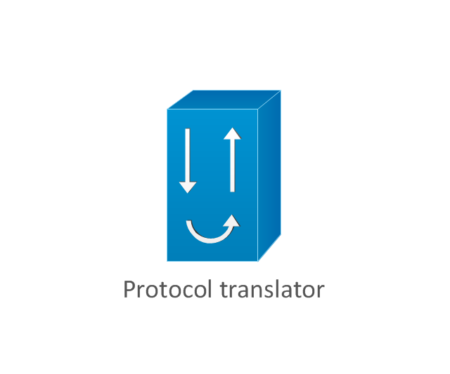
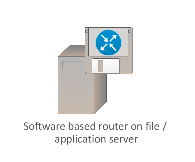
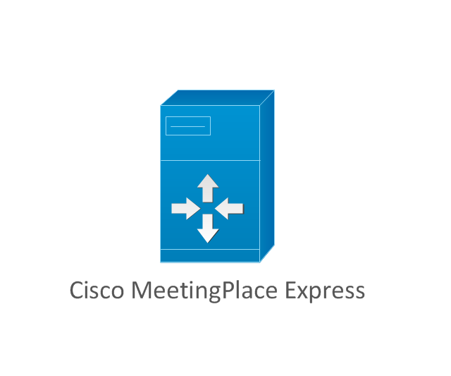
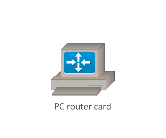
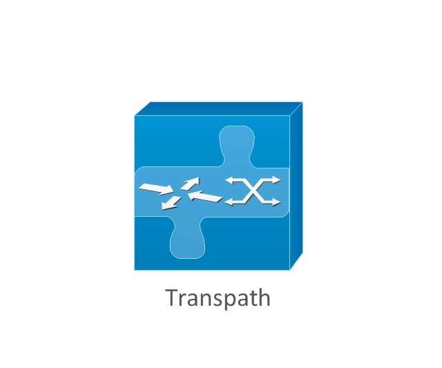
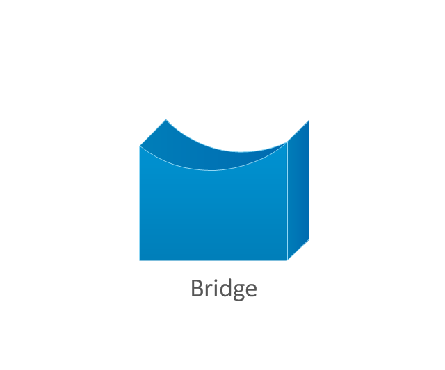
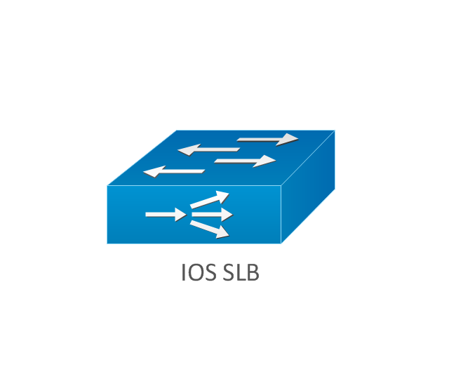
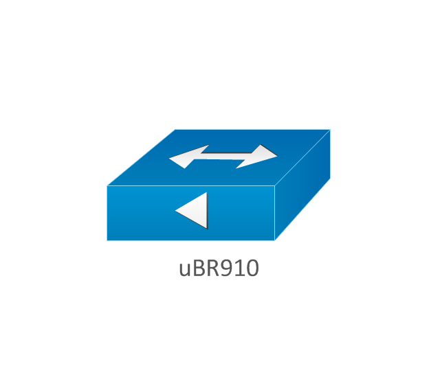
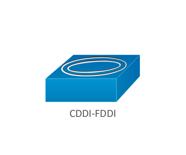
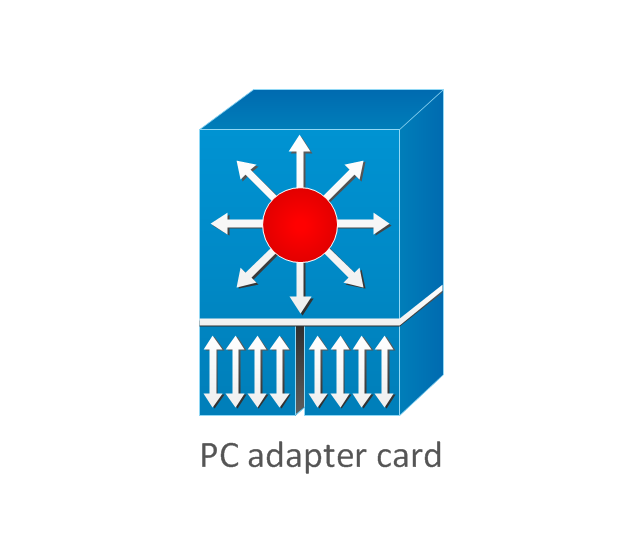
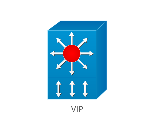
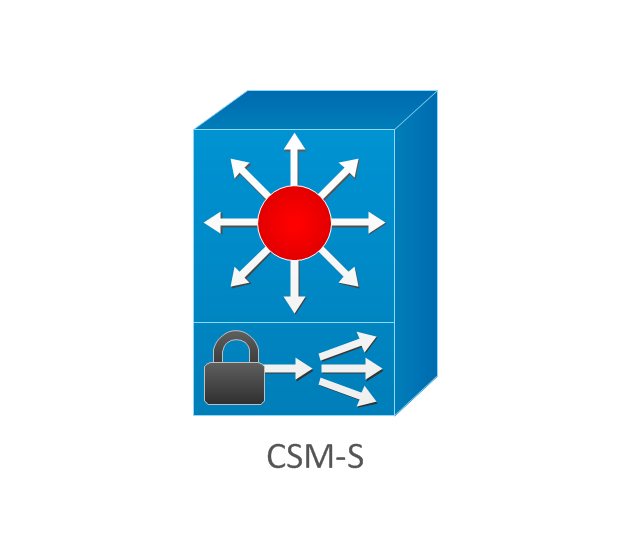
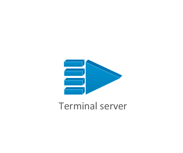
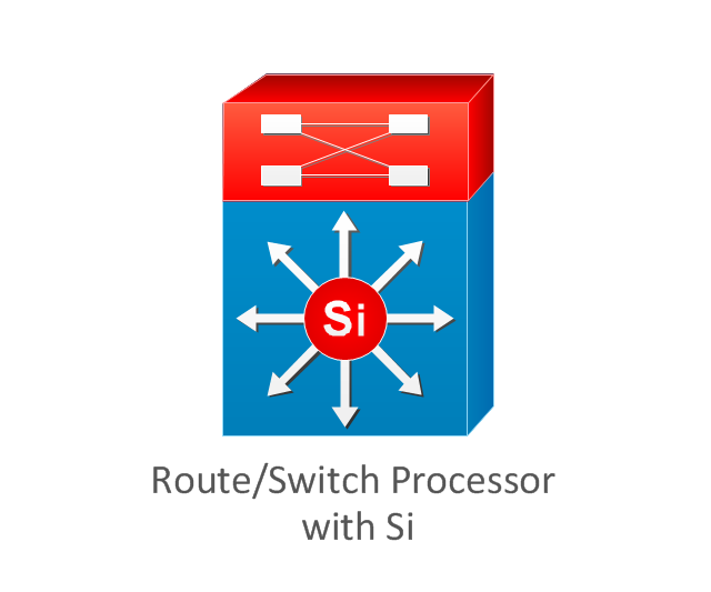
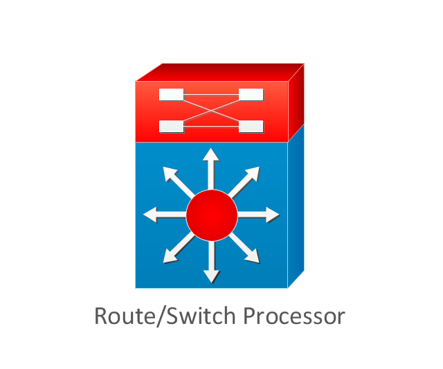
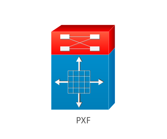
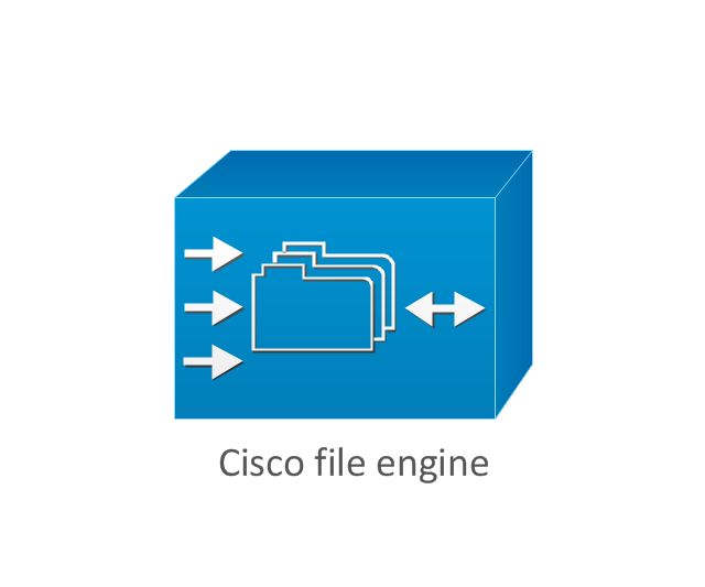
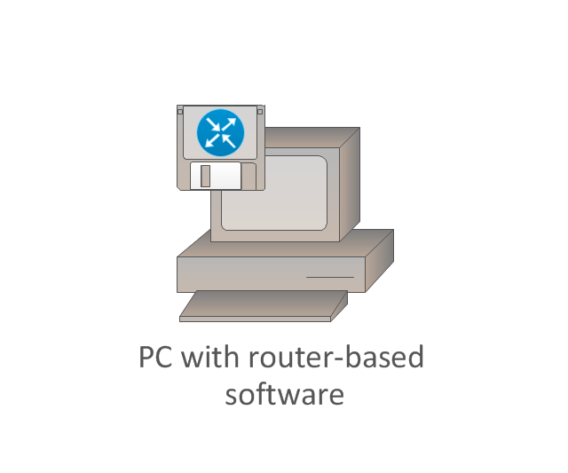
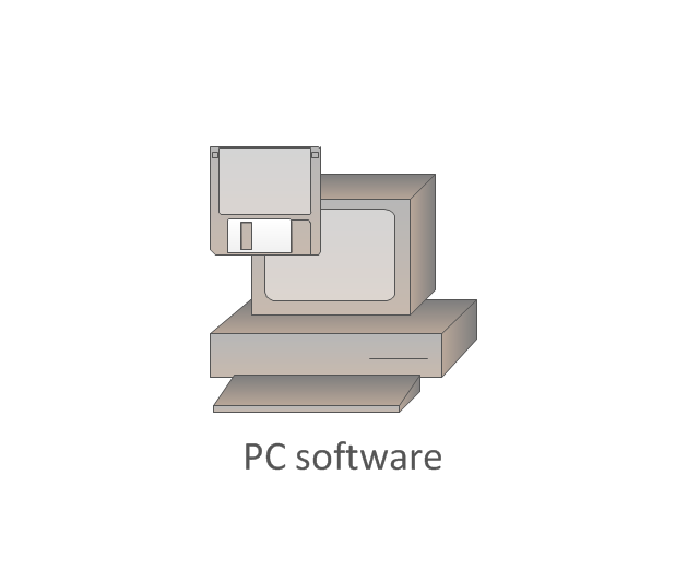
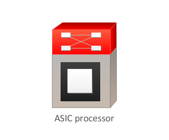
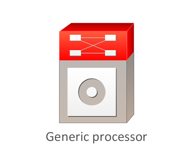
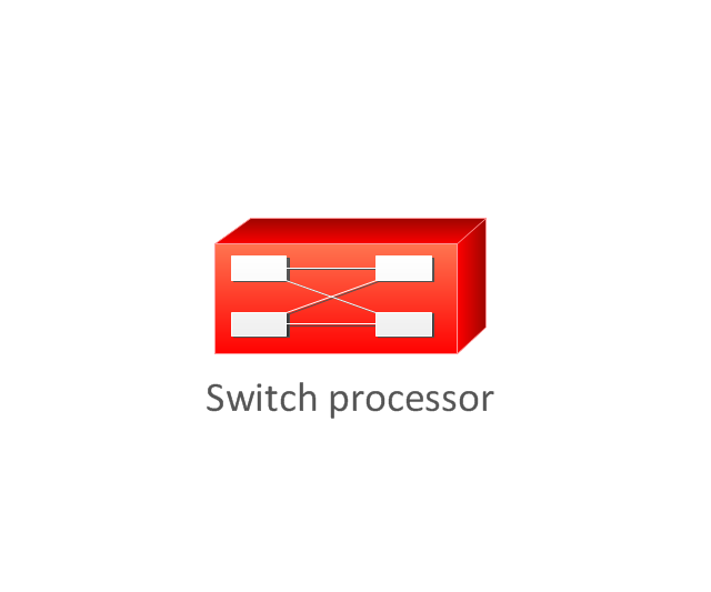
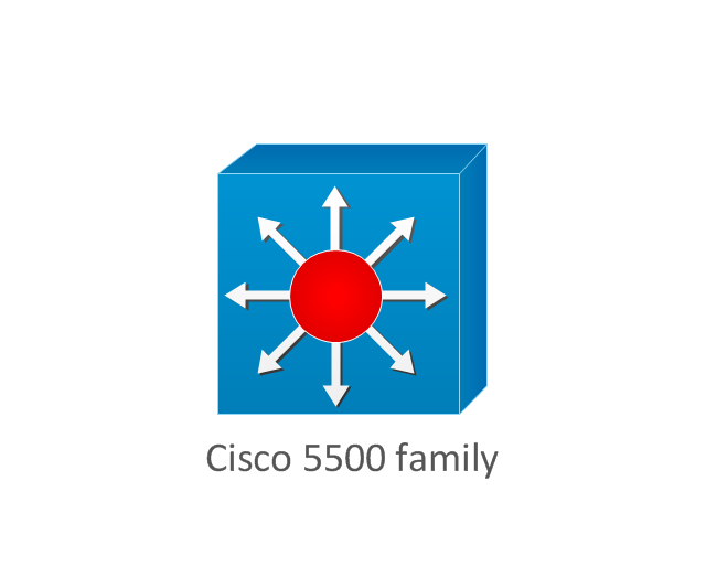
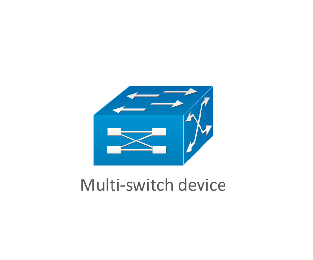
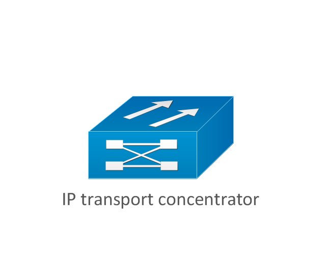
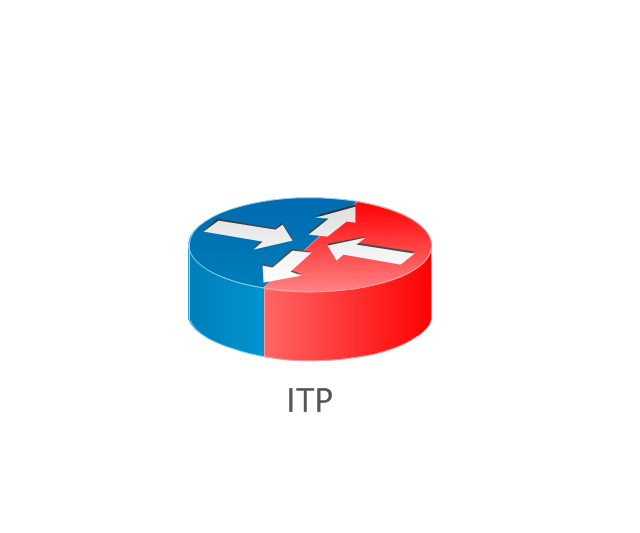
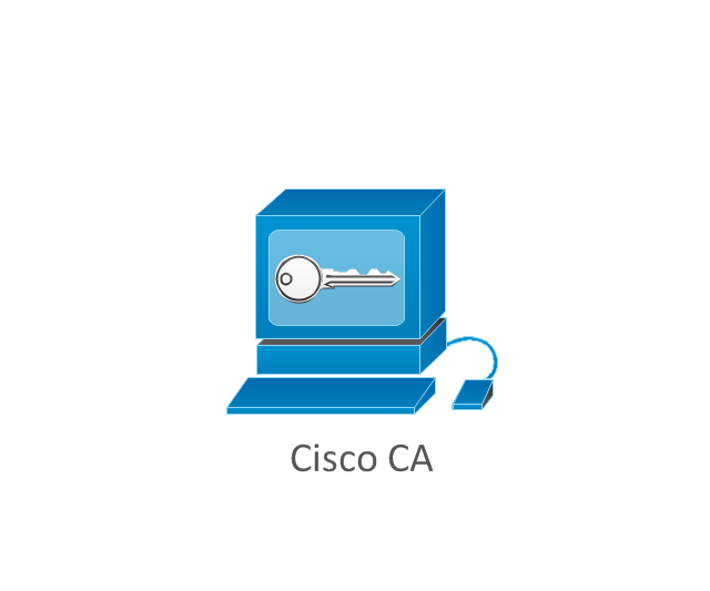
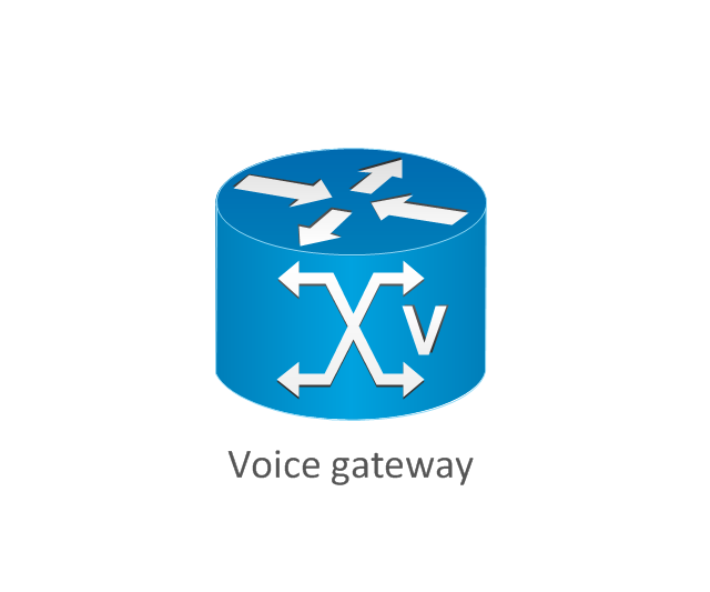
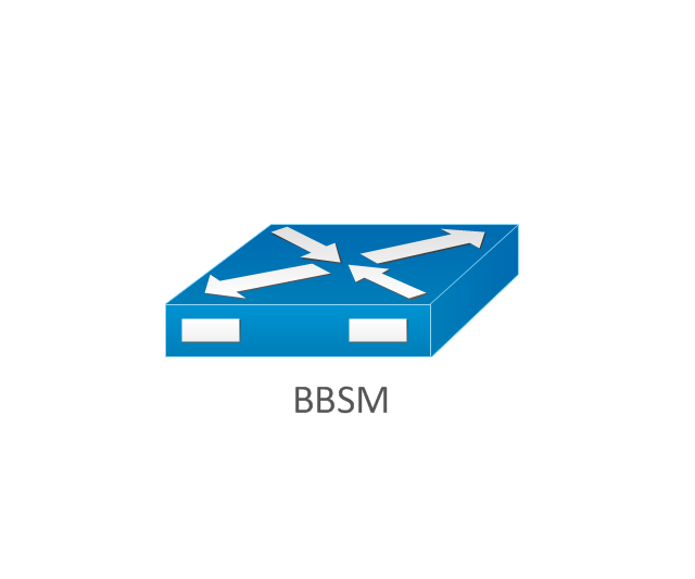
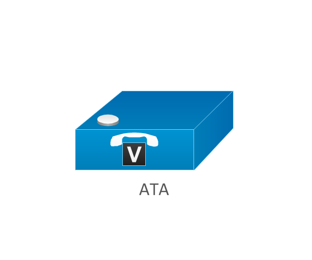
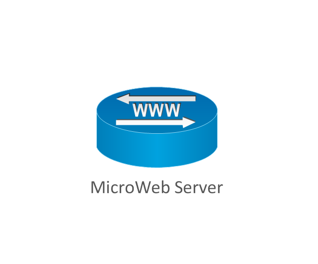
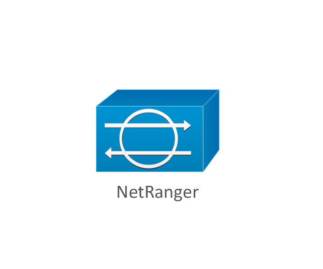
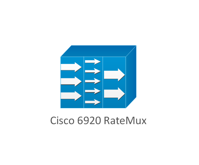
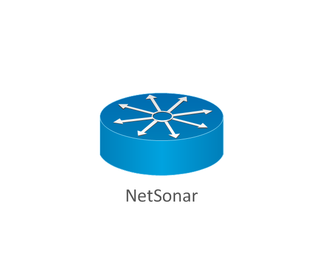
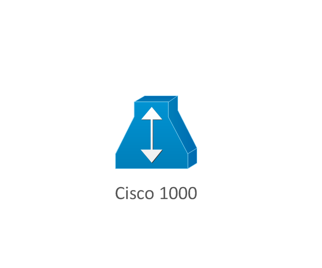
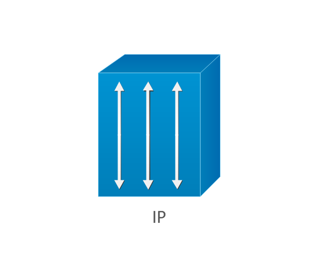
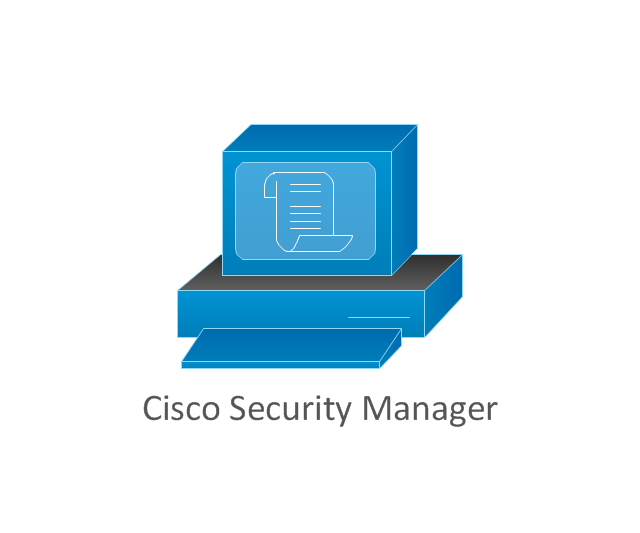
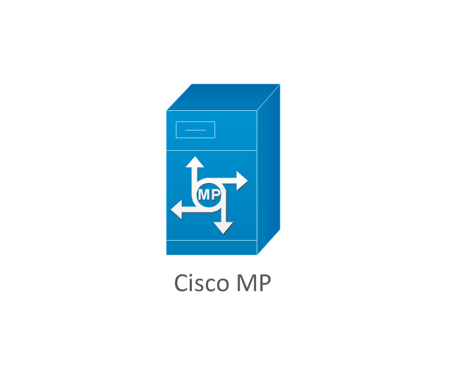
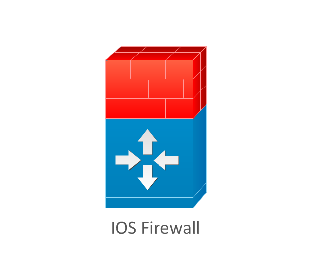
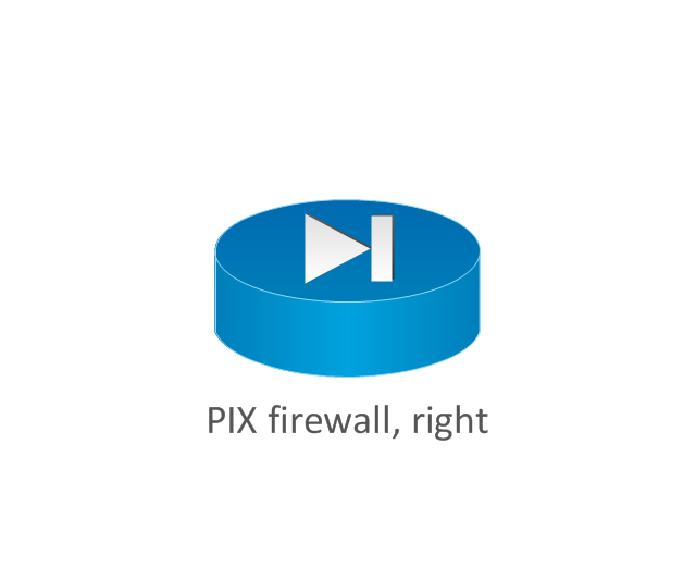
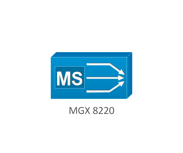
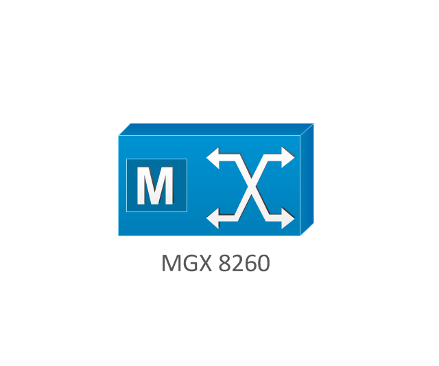
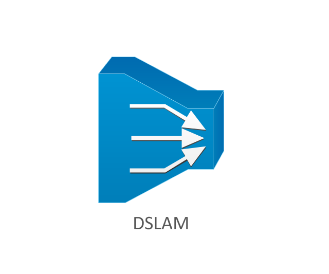
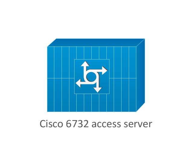
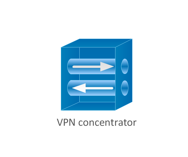
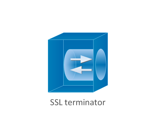
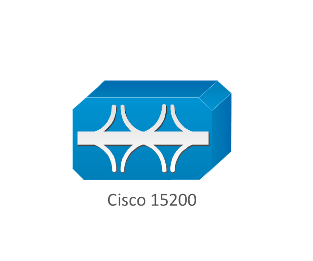
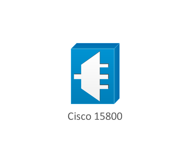
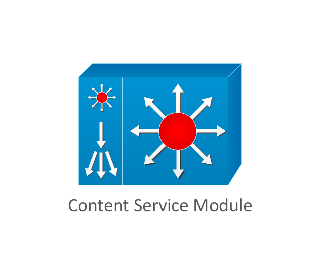
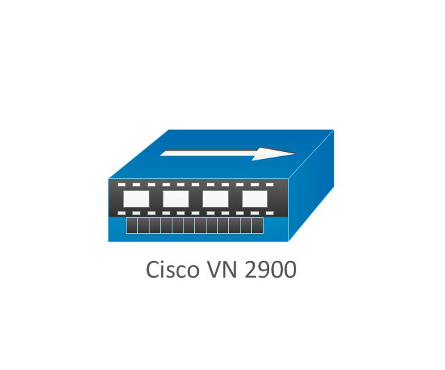
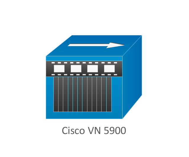
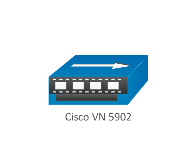
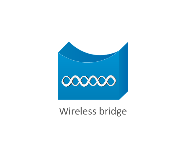
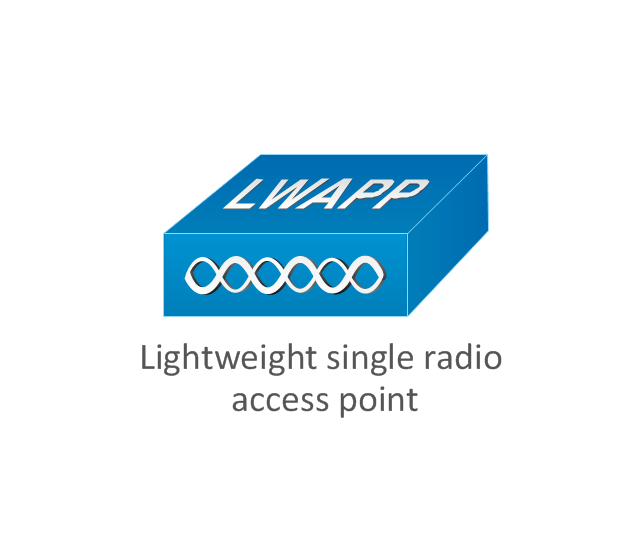
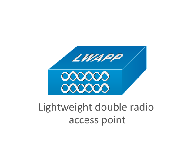
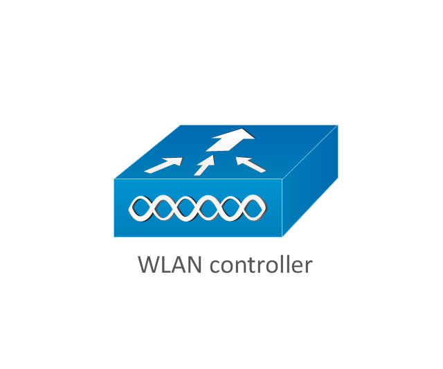
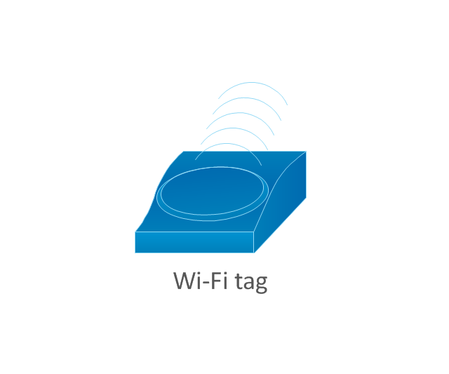
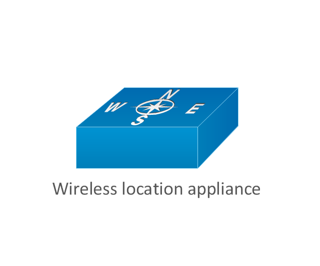
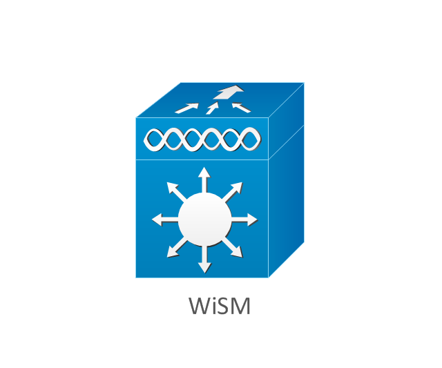
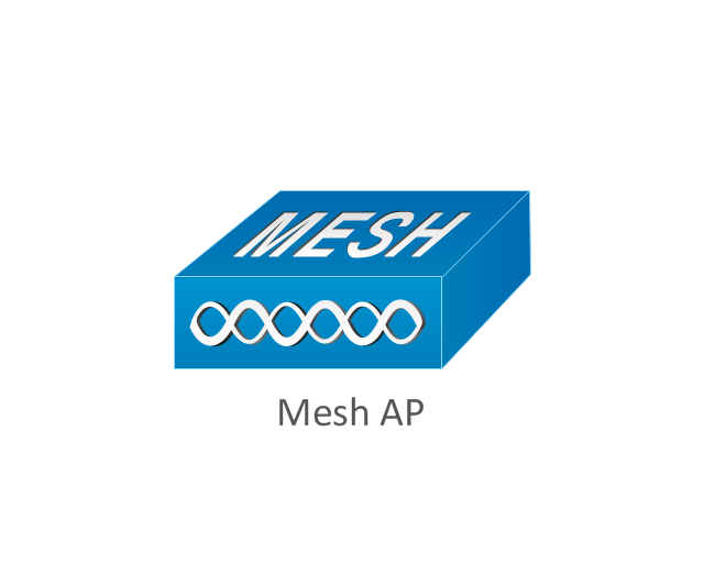
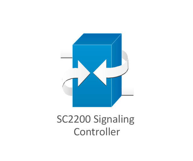
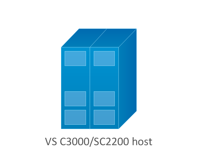
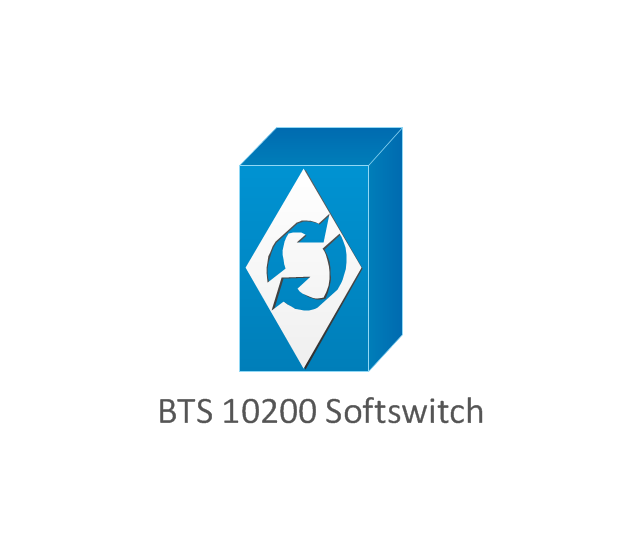
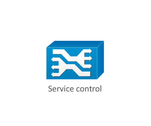
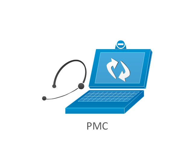
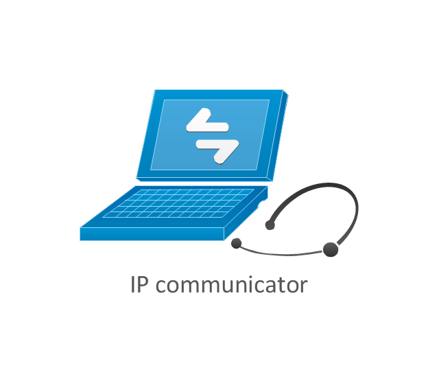
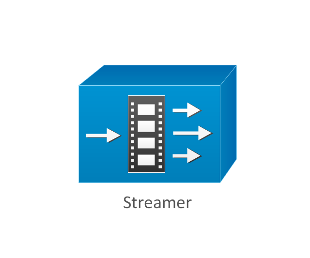
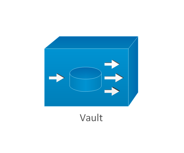
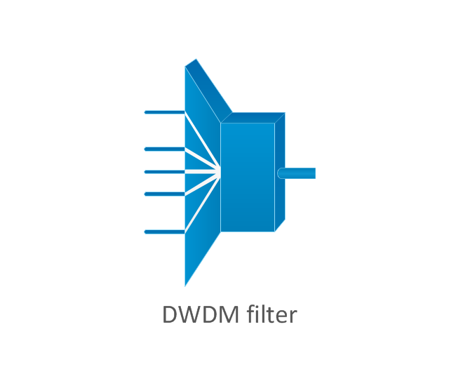
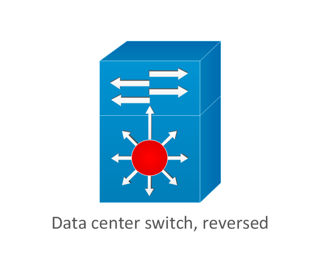
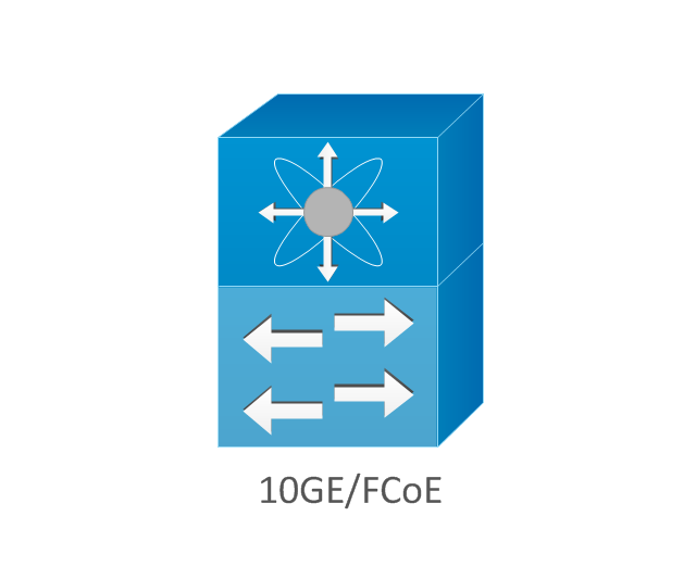
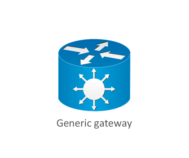
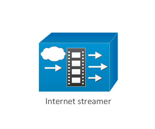
The vector stencils library "Cisco products additional" contains 141 symbols of computer network devices and equipment for drawing Cisco network diagrams.
The symbols example "Cisco products additional - Vector stencils library" was created using the ConceptDraw PRO diagramming and vector drawing software extended with the Cisco Network Diagrams solution from the Computer and Networks area of ConceptDraw Solution Park.
www.conceptdraw.com/ solution-park/ computer-networks-cisco
Network Gateway Router
Special libraries of highly detailed, accurate shapes and computer graphics, servers, hubs, switches, printers, mainframes, face plates, routers etc.
The vector stencils library "Cisco products additional" contains 141 symbols of computer network devices and equipment for drawing Cisco network diagrams.
The symbols example "Cisco products additional - Vector stencils library" was created using the ConceptDraw PRO diagramming and vector drawing software extended with the Cisco Network Diagrams solution from the Computer and Networks area of ConceptDraw Solution Park.
www.conceptdraw.com/ solution-park/ computer-networks-cisco
The symbols example "Cisco products additional - Vector stencils library" was created using the ConceptDraw PRO diagramming and vector drawing software extended with the Cisco Network Diagrams solution from the Computer and Networks area of ConceptDraw Solution Park.
www.conceptdraw.com/ solution-park/ computer-networks-cisco
The vector stencils library "Cisco network topology" contains 89 symbols of Cisco network devices and design elements for drawing computer network topology diagrams.
"There are two basic categories of network topologies:
(1) Physical topologies,
(2) Logical topologies.
The shape of the cabling layout used to link devices is called the physical topology of the network. This refers to the layout of cabling, the locations of nodes, and the interconnections between the nodes and the cabling. The physical topology of a network is determined by the capabilities of the network access devices and media, the level of control or fault tolerance desired, and the cost associated with cabling or telecommunications circuits.
The logical topology in contrast, is the way that the signals act on the network media, or the way that the data passes through the network from one device to the next without regard to the physical interconnection of the devices." [Network topology. Wikipedia]
The symbols example "Cisco network topology - Vector stencils library" was created using the ConceptDraw PRO diagramming and vector drawing software extended with the Cisco Network Diagrams solution from the Computer and Networks area of ConceptDraw Solution Park.
www.conceptdraw.com/ solution-park/ computer-networks-cisco
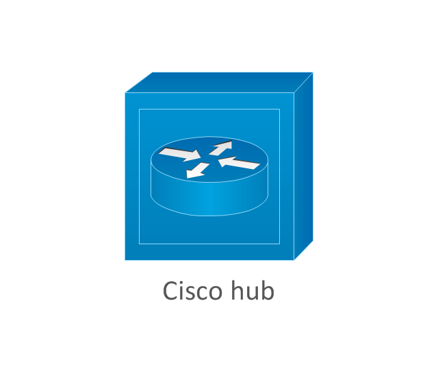
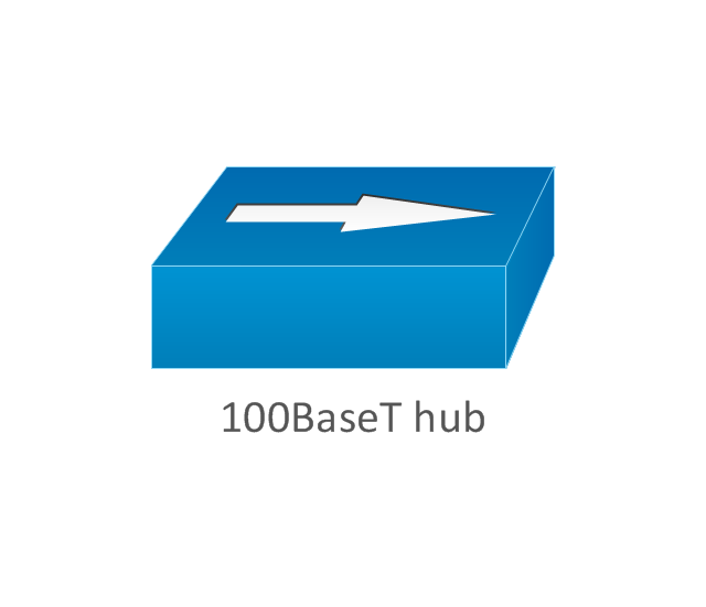
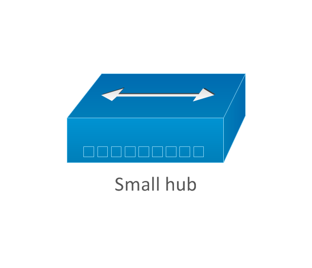
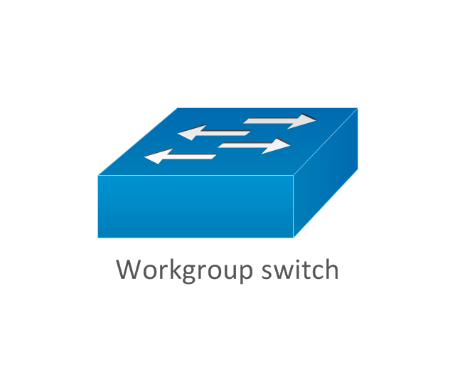
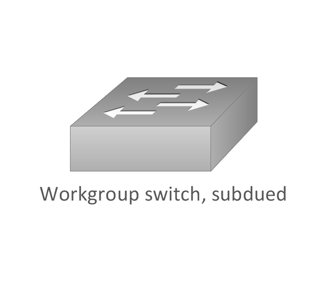
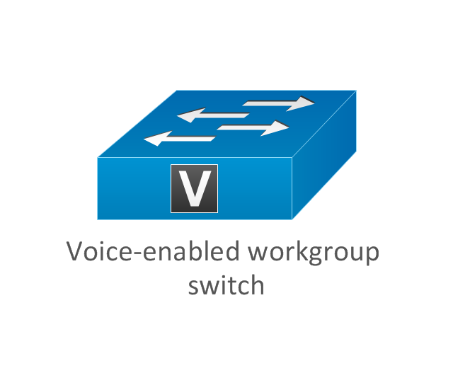
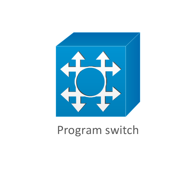
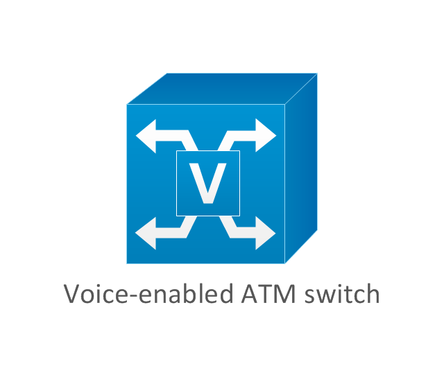
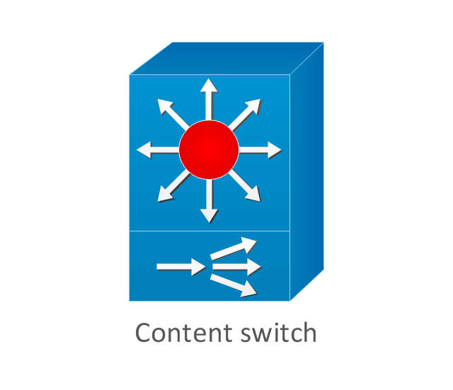
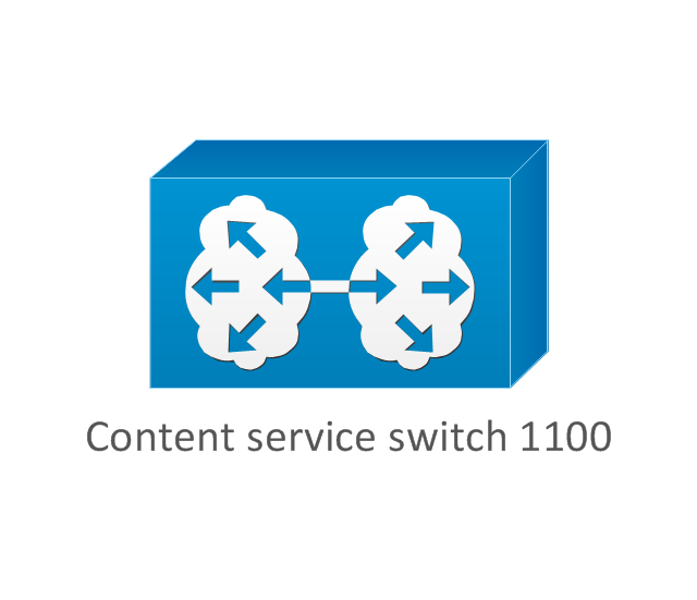
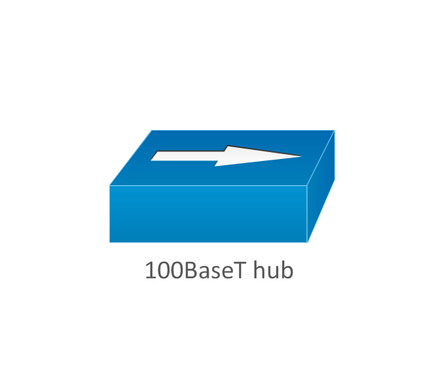
The vector stencils library "Cisco switches and hubs" contains 26 symbols of Cisco switches and hubs for drawing computer network diagrams.
"A switch is a device used on a computer network to physically connect devices together. Multiple cables can be connected to a switch to enable networked devices to communicate with each other. Switches manage the flow of data across a network by only transmitting a received message to the device for which the message was intended. Each networked device connected to a switch can be identified using a MAC address, allowing the switch to regulate the flow of traffic. This maximises security and efficiency of the network. Because of these features, a switch is often considered more "intelligent" than a network hub. Hubs neither provide security, or identification of connected devices. This means that messages have to be transmitted out of every port of the hub, greatly degrading the efficiency of the network." [Network switch. Wikipedia]
"An Ethernet hub, active hub, network hub, repeater hub, multiport repeater or hub is a device for connecting multiple Ethernet devices together and making them act as a single network segment. It has multiple input/ output (I/ O) ports, in which a signal introduced at the input of any port appears at the output of every port except the original incoming. A hub works at the physical layer (layer 1) of the OSI model. The device is a form of multiport repeater. Repeater hubs also participate in collision detection, forwarding a jam signal to all ports if it detects a collision." [Ethernet hub. Wikipedia]
The symbols example "Cisco switches and hubs - Vector stencils library" was created using the ConceptDraw PRO diagramming and vector drawing software extended with the Cisco Network Diagrams solution from the Computer and Networks area of ConceptDraw Solution Park.
www.conceptdraw.com/ solution-park/ computer-networks-cisco
This IVR diagram sample illustrates how ENUM works by giving an example: Subscriber A sets out to call Subscriber B:
1. The User Agent of an ENUM-enabled subscriber terminal device, or a PBX, or a Gateway, translates the request for the number +34 98 765 4321 in accordance with the rule described in RFC 3761 into the ENUM domain 1.2.3.4.5.6.7.8.9.4.3.e164.arpa.
2. A request is sent to the Domain Name System (DNS) asking it to look up the ENUM domain 1.2.3.4.5.6.7.8.9.4.3.e164.arpa.
3. The query returns a result in the form of so called Naming Authority Pointer Resource NAPTR records, as per RFC 3403. In the example above, the response is an address that can be reached in the Internet using the VoIP protocol, SIP per RFC 3261.
4. The terminal application now sets up a communication link, and the call is routed via the Internet.
This IVR diagram sample was designed on the base of the Wikimedia Commons file: Ejemplo ENUM.jpg. [commons.wikimedia.org/ wiki/ File:Ejemplo_ ENUM.jpg]
"Being able to dial telephone numbers the way customers have come to expect is considered crucial for the convergence of classic telephone service (PSTN) and Internet telephony (Voice over IP, VoIP), and for the development of new IP multimedia services. The problem of a single universal personal identifier for multiple communication services can be solved with different approaches. One simple approach is the Electronic Number Mapping System (ENUM), developed by the IETF, using existing E.164 telephone numbers, protocols and infrastructure to indirectly access different services available under a single personal identifier. ENUM also permits connecting the IP world to the telephone system in a seamless manner." [Telephone number mapping. Wikipedia]
The IVR diagram example "Example ENUM" was designed using ConceptDraw PRO diagramming and vector drawing software extended with the Interactive Voice Response Diagrams solution from the Computer and Networks area of ConceptDraw Solution Park.
- Voice Gateway Png
- VoIP call with SIM box and gateway | Interactive Voice Response ...
- Network Topologies | Voip Card Png Symbol
- VoIP call with SIM box and gateway | Design elements - Media ...
- VoIP call with SIM box and gateway | Process Flowchart | How to ...
- VoIP call with SIM box and gateway | IVR mobile - Vector stencils ...
- Interactive Voice Response Diagrams | Mobile Phone Call Png
- Png Gateway
- VoIP call with SIM box and gateway | Android GUI | Sim Wifi Icon Png
- Vertical Firewall Image Png
- Cisco Voice Gateway Png
- VoIP call with SIM box and gateway | IVR systems architecture ...
- Brick Wall Drawing Vertical Png
- Cisco products additional - Vector stencils library | Wlc Symbol Png
- Cisco Bridge Symbol Png
- IVR systems architecture | VoIP call with SIM box and gateway ...
- VoIP call with SIM box and gateway | Android UI Design | Android ...
- VoIP call with SIM box and gateway | Flowchart design. Flowchart ...
- Ios 10 Clock Icon Png
- VoIP call with SIM box and gateway | Chemistry Equation Symbols ...

-cisco-products-additional---vector-stencils-library.png--diagram-flowchart-example.png)
-cisco-products-additional---vector-stencils-library.png--diagram-flowchart-example.png)
-cisco-products-additional---vector-stencils-library.png--diagram-flowchart-example.png)
-cisco-products-additional---vector-stencils-library.png--diagram-flowchart-example.png)

-cisco-products-additional---vector-stencils-library.png--diagram-flowchart-example.png)
-cisco-products-additional---vector-stencils-library.png--diagram-flowchart-example.png)
-cisco-products-additional---vector-stencils-library.png--diagram-flowchart-example.png)
-cisco-products-additional---vector-stencils-library.png--diagram-flowchart-example.png)
-cisco-products-additional---vector-stencils-library.png--diagram-flowchart-example.png)
-cisco-products-additional---vector-stencils-library.png--diagram-flowchart-example.png)

-cisco-products-additional---vector-stencils-library.png--diagram-flowchart-example.png)
-cisco-products-additional---vector-stencils-library.png--diagram-flowchart-example.png)
-cisco-products-additional---vector-stencils-library.png--diagram-flowchart-example.png)
-cisco-products-additional---vector-stencils-library.png--diagram-flowchart-example.png)
-cisco-products-additional---vector-stencils-library.png--diagram-flowchart-example.png)



-cisco-network-topology---vector-stencils-library.png--diagram-flowchart-example.png)
-cisco-network-topology---vector-stencils-library.png--diagram-flowchart-example.png)


-cisco-network-topology---vector-stencils-library.png--diagram-flowchart-example.png)


-cisco-network-topology---vector-stencils-library.png--diagram-flowchart-example.png)


-cisco-network-topology---vector-stencils-library.png--diagram-flowchart-example.png)


