Circuits and Logic Diagram Software

 Electrical Engineering
This solution extends ConceptDraw DIAGRAM.9.5 (or later) with electrical engineering samples, electrical schematic symbols, electrical diagram symbols, templates and libraries of design elements, to help you design electrical schematics, digital and analog
Basic Diagramming


Technical Drawing Software

Electrical Symbols — Inductors

 Business Diagrams
The Business Diagrams Solution extends ConceptDraw DIAGRAM with an extensive collection of professionally designed illustrative samples and a wide variety of vector stencils libraries, which are the real help for all business-related people, business analysts, business managers, business advisers, marketing experts, PR managers, knowledge workers, scientists, and other stakeholders allowing them to design the bright, neat, expressive and attractive Bubble Diagrams, Circle-Spoke Diagrams, Circular Arrows Diagrams, and Venn Diagrams with different quantity of sets in just minutes; and then successfully use them in documents, reports, statistical summaries, and presentations of any style.
 Mechanical Engineering
This solution extends ConceptDraw DIAGRAM.9 mechanical drawing software (or later) with samples of mechanical drawing symbols, templates and libraries of design elements, for help when drafting mechanical engineering drawings, or parts, assembly, pneumatic,
Mechanical Drawing Symbols

Functional Block Diagram

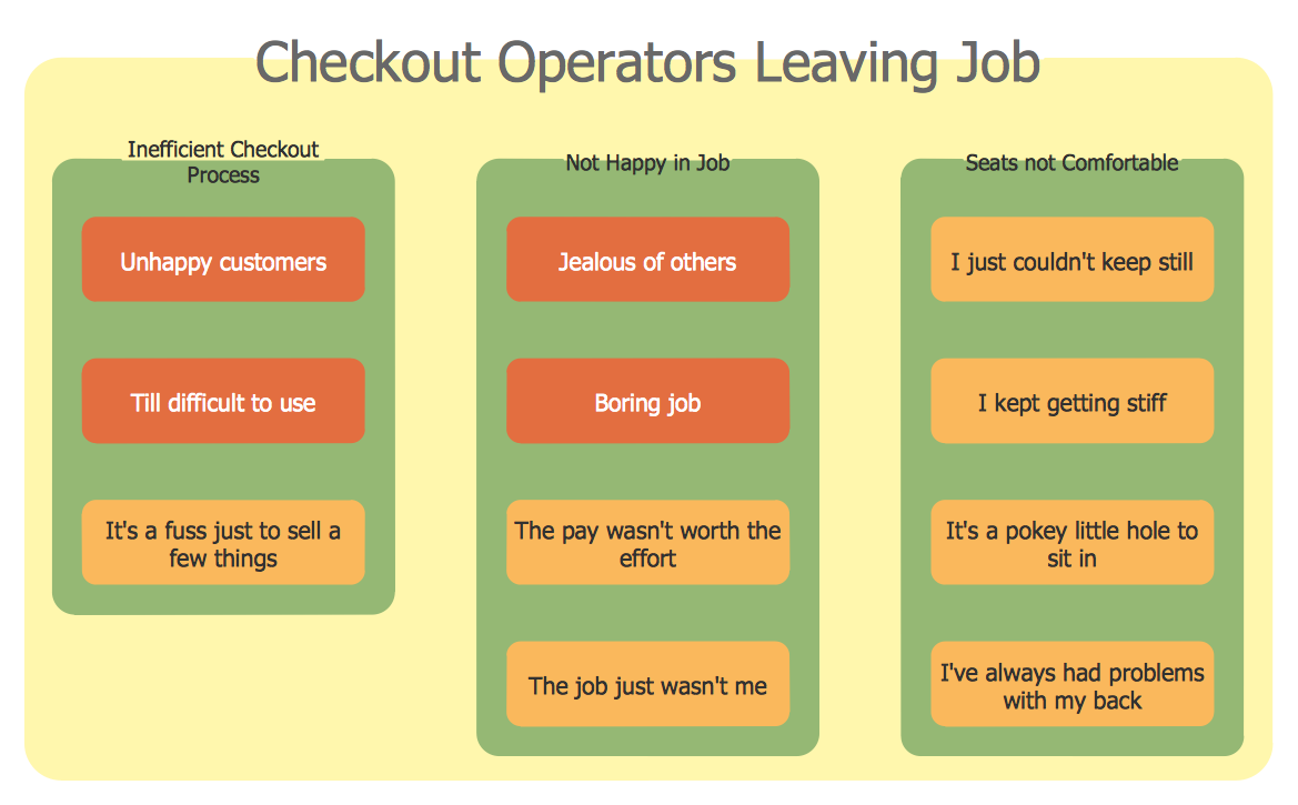
Affinity Diagram
- Basic Diagramming | Electrical Symbols, Electrical Diagram ...
- Venn Diagram Examples for Problem Solving. Venn Diagram as a ...
- Venn Diagram Maker | Venn Diagram Examples for Problem Solving ...
- Venn Diagram Examples for Problem Solving. Venn Diagram as a ...
- Circuits and Logic Diagram Software | How to Simplify Flow Charting ...
- Venn Diagram Examples for Problem Solving. Venn Diagram as a ...
- Venn Diagrams | ConceptDraw Solution Park | Venn Diagram ...
- Circuits and Logic Diagram Software | Electrical Symbols — Logic ...
- Software To Draw Circuit Diagram
- Biology Drawing Software | Physics Diagrams | Chemistry Drawing ...