This site uses cookies. By continuing to browse the ConceptDraw site you are agreeing to our Use of Site Cookies.
The vector stencils library "Welding" contains 38 welding joint symbols to identify fillets, contours, resistance seams, grooves, surfacing, and backing.
Use it to indicate welding operations on working drawings in the ConceptDraw PRO diagramming and vector drawing software extended with the Mechanical Engineering solution from the Engineering area of ConceptDraw Solution Park.
www.conceptdraw.com/ solution-park/ engineering-mechanical
Additional arrow
Additional arrow, arrow,
Text block
Text block,
Fillet
Fillet, fillet, weld,
Slot / plug
Slot / plug, slot, plug, weld,
Stud
Stud, stud,
Resistance seam
Resistance seam, resistance seam weld,
Backing
Backing, back, backing,
Surfacing
Surfacing, surfacing,
Flange corner
Flange corner, flange corner, flanged corner groove,
Flange edge
Flange edge, flange edge, weld, flanged edge groove,
Square groove
Square groove, square groove,
V-groove
V-groove, V-groove,
Bevel groove
Bevel groove, bevel groove,
U-groove
U-groove, U-groove,
J-groove
J-groove, J-groove,
Flare V groove
Flare V groove, flare V groove, flared-V groove,
Flare bevel groove
Flare bevel groove, flare bevel groove, flared-bevel groove,
Scarf
Scarf, scarf, bronzed joint,
Melt through weld
Melt through weld, melt through weld,
Field weld
Field weld, field weld,
Backing / spacer
Backing / spacer, backing, spacer,
Insert
Insert, insert, consumable insert,
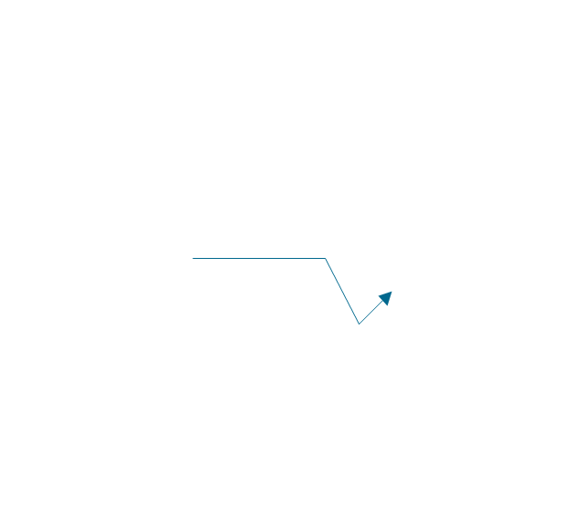
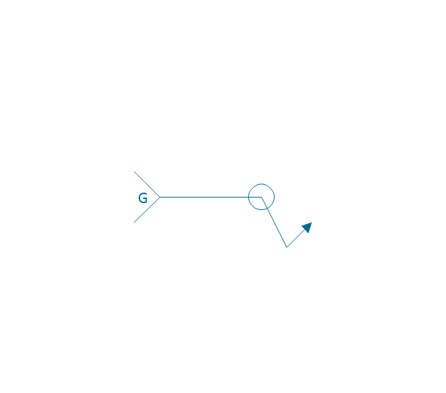
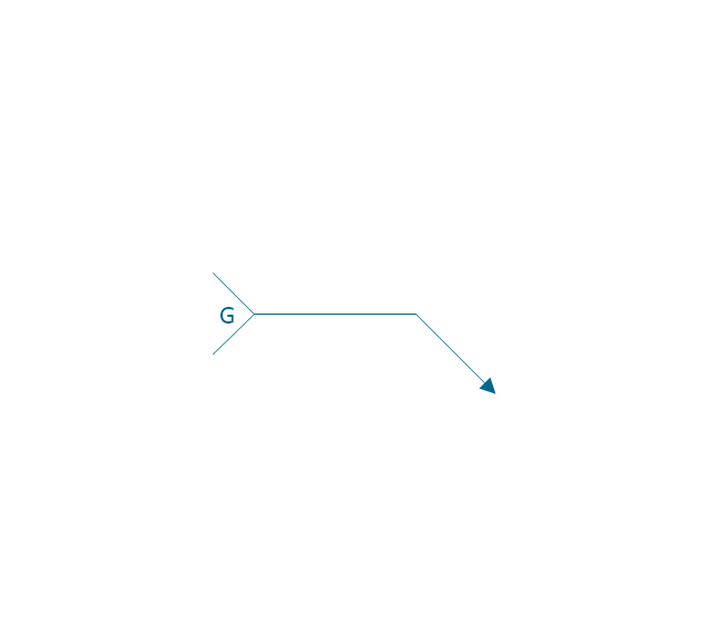
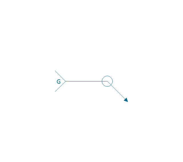
Arrow with bend
Arrow with bend, arrow, bend,
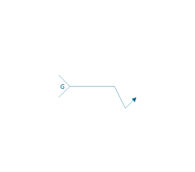
Arrow with bend, tail
Arrow with bend, tail, arrow, bend,
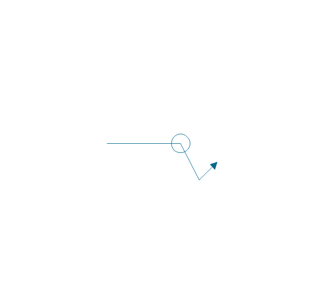
Arrow with bend, circle
Arrow with bend, circle, arrow, bend,
Arrow with bend, circle, tail
Arrow with bend, circle, tail, arrow, bend,
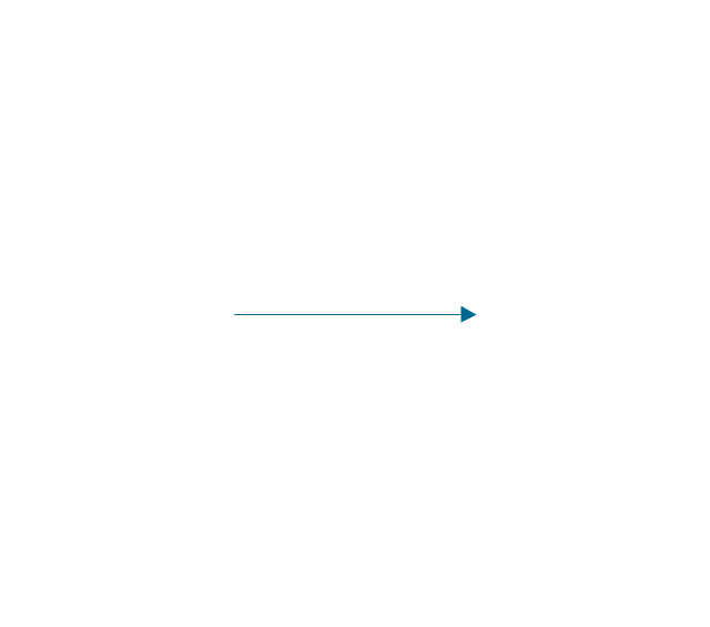
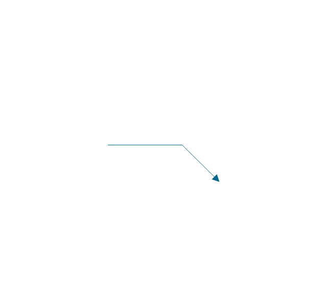
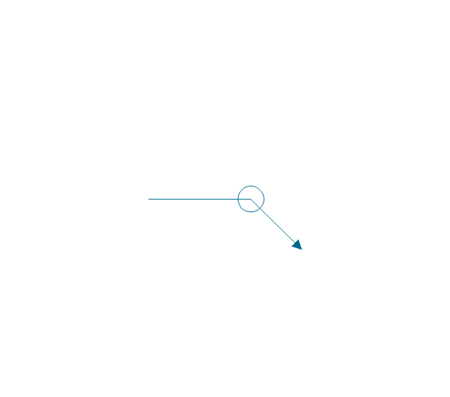
Arrow
Arrow, arrow,
Arrow, tail
Arrow, tail, arrow,
Arrow, circle
Arrow, circle, arrow,
Arrow, circle, tail
Arrow, circle, tail, arrow,
Spot
Spot, spot, projection, weld,
Projection weld
Projection weld, spot, projection, weld,
Contour, concave
Contour, concave, contour, concave, weld,
Contour, convex
Contour, convex, contour, convex, weld,
Contour, flush
Contour, flush, contour, flush, weld,
Contour angled, concave
Contour angled, concave, contour, angled, concave, weld,
Contour angled, convex
Contour angled, convex, contour, angled, convex, weld,
Contour angled, flush
Contour angled, flush, contour, angled, flush, weld,
Square butt weld
Square butt weld, square butt weld,
Closed square butt weld
Closed square butt weld, closed square butt weld,
Single-bevel butt weld
Single-bevel butt weld, single bevel butt weld,
Double-bevel butt weld
Double-bevel butt weld, double bevel butt weld,
Single-V butt weld
Single-V butt weld, single-V butt weld,
Double-V butt weld
Double-V butt weld, double-V butt weld,
Single-J butt weld
Single-J butt weld, single-J butt weld,
Double-J butt weld
Double-J butt weld, double-J butt weld,
Single-U butt weld
Single-U butt weld, single-U butt weld,
Double-U butt weld
Double-U butt weld, double-U butt weld,
Flange butt weld
Flange butt weld, flange butt weld,
Tee butt weld
Tee butt weld, tee butt weld,
Flare butt weld
Flare butt weld, flare butt weld,
Square butt joint
Square butt joint, square butt joint,
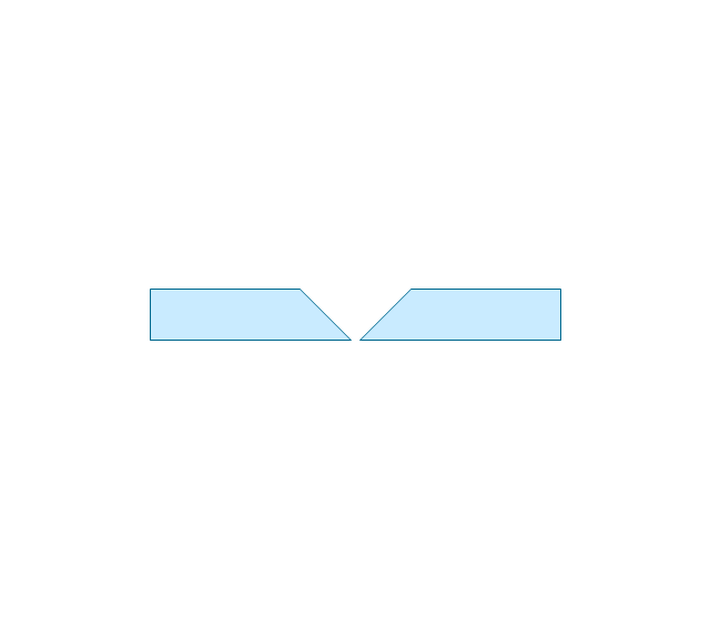
Single V preparation joint
Single V preparation joint, single V preparation joint,
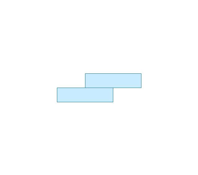
Lap joint
Lap joint, lap joint,
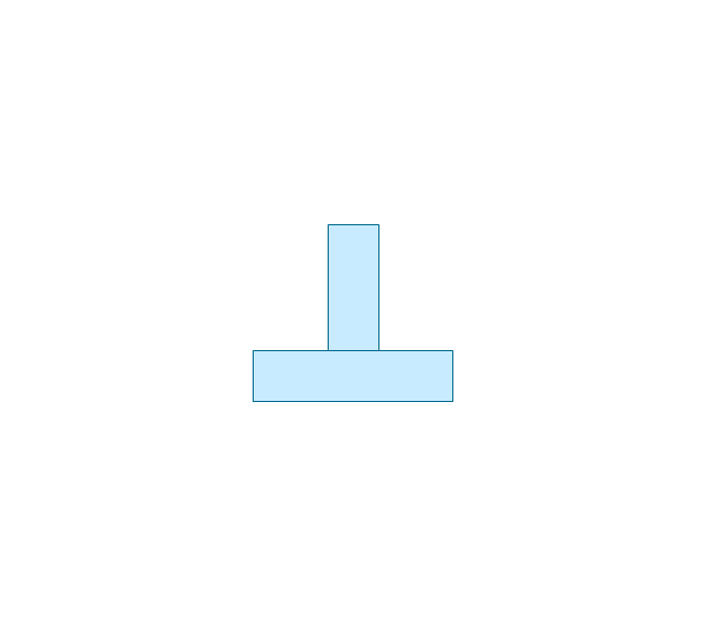
T-joint
T-joint, T-joint,
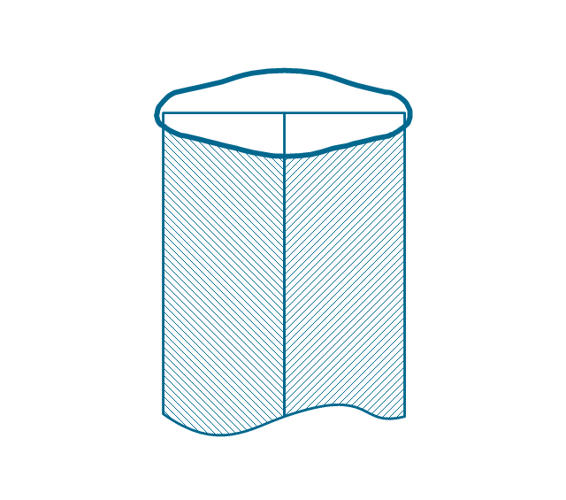
Butt weld
Butt weld, butt weld,
Butt weld, single-V
Butt weld, single-V, butt weld,
Bilateral lap weld
Bilateral lap weld, bilateral lap weld,
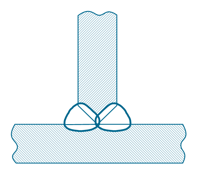
Tee weld
Tee weld, tee weld,
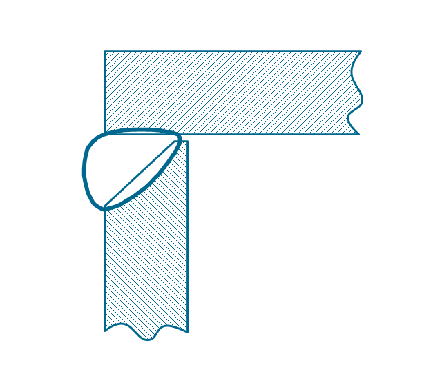
Angular weld
Angular weld, angular weld,
Mechanical weld
Mechanical weld, mechanical weld,
"Hydraulics is a topic in applied science and engineering dealing with the mechanical properties of liquids. At a very basic level hydraulics is the liquid version of pneumatics. Fluid mechanics provides the theoretical foundation for hydraulics, which focuses on the engineering uses of fluid properties. In fluid power, hydraulics is used for the generation, control, and transmission of power by the use of pressurized liquids. Hydraulic topics range through some part of science and most of engineering modules, and cover concepts such as pipe flow, dam design, fluidics and fluid control circuitry, pumps, turbines, hydropower, computational fluid dynamics, flow measurement, river channel behavior and erosion." [Hydraulics. Wikipedia]
This hydraulic schematic example was redrawn using ConceptDraw PRO diagramming and vector drawing software from the Wikimedia Commons file: Skjematikk.GIF.
[commons.wikimedia.org/ wiki/ File:Skjematikk.GIF]
This file is licensed under the Creative Commons Attribution-Share Alike 3.0 Unported license.
[creativecommons.org/ licenses/ by-sa/ 3.0/ deed.en]
The engineering drawing example "Hydraulic schematic" was created using the ConceptDraw PRO diagramming and vector drawing software extended with the Mechanical Engineering solution from the Engineering area of ConceptDraw Solution Park.
Hydraulic schematic example
Hydraulic schematic example, restrictor valve, reservoir, drain, return, pressure relief, sequence valve, hydraulic pump, double-acting, magnetic cylinder,
The vector stencils library "Welding" contains 38 welding joint symbols to identify fillets, contours, resistance seams, grooves, surfacing, and backing.
Use it to indicate welding operations on working drawings.
"Welding is a fabrication or sculptural process that joins materials, usually metals or thermoplastics, by causing coalescence. This is often done by melting the workpieces and adding a filler material to form a pool of molten material (the weld pool) that cools to become a strong joint, with pressure sometimes used in conjunction with heat, or by itself, to produce the weld. This is in contrast with soldering and brazing, which involve melting a lower-melting-point material between the workpieces to form a bond between them, without melting the workpieces.
Many different energy sources can be used for welding, including a gas flame, an electric arc, a laser, an electron beam, friction, and ultrasound.
Welds can be geometrically prepared in many different ways. The five basic types of weld joints are the butt joint, lap joint, corner joint, edge joint, and T-joint (a variant of this last is the cruciform joint). Other variations exist as well - for example, double-V preparation joints are characterized by the two pieces of material each tapering to a single center point at one-half their height. Single-U and double-U preparation joints are also fairly common - instead of having straight edges like the single-V and double-V preparation joints, they are curved, forming the shape of a U. Lap joints are also commonly more than two pieces thick - depending on the process used and the thickness of the material, many pieces can be welded together in a lap joint geometry." [Welding. Wikipedia]
The shapes example "Design elements - Welding" was created using the ConceptDraw PRO diagramming and vector drawing software extended with the Mechanical Engineering solution from the Engineering area of ConceptDraw Solution Park.
Welding joint symbols
Welding joint symbols, surfacing, stud, square groove, spot, projection, weld, slot, plug, weld, scarf, bronzed joint, resistance seam weld, melt through weld, insert, consumable insert, flare bevel groove, flared-bevel groove, flare V groove, flared-V groove, flange edge, weld, flanged edge groove, flange corner, flanged corner groove, fillet, weld, field weld, contour, flush, weld, contour, convex, weld, contour, concave, weld, contour, angled, flush, weld, contour, angled, convex, weld, contour, angled, concave, weld, bevel groove, backing, spacer, back, backing, arrow, bend, arrow, V-groove, U-groove, J-groove,
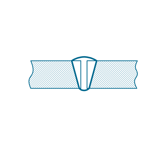
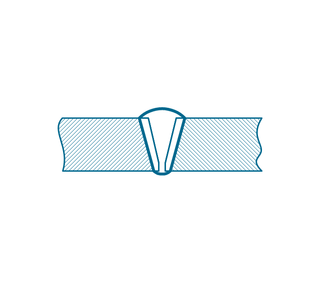
This engineering drawing shows different types of geometry of butt welds.
"Welds can be geometrically prepared in many different ways. The five basic types of weld joints are the butt joint, lap joint, corner joint, edge joint, and T-joint (a variant of this last is the cruciform joint). Other variations exist as well - for example, double-V preparation joints are characterized by the two pieces of material each tapering to a single center point at one-half their height. Single-U and double-U preparation joints are also fairly common - instead of having straight edges like the single-V and double-V preparation joints, they are curved, forming the shape of a U. Lap joints are also commonly more than two pieces thick - depending on the process used and the thickness of the material, many pieces can be welded together in a lap joint geometry." [Welding. Wikipedia]
This engineering drawing example was redesigned using the ConceptDraw PRO diagramming and vector drawing software from the Wikimedia Commons file: Butt Weld Geometry.GIF.
[commons.wikimedia.org/ wiki/ File:Butt_ Weld_ Geometry.GIF]
The engineering drawing example "Butt weld geometry" is included in the Mechanical Engineering solution from the Engineering area of ConceptDraw Solution Park.
Welding joint diagram
Welding joint diagram, tee butt weld, square butt weld, single-V butt weld, single-U butt weld, single-J butt weld, single bevel butt weld, flare butt weld, flange butt weld, double-V butt weld, double-U butt weld, double-J butt weld, double bevel butt weld, closed square butt weld,

mechanical engineering, mechanical design software, mechanical drawing symbols, mechanical drawing software Mechanical Engineering

mechanical engineering, mechanical design software, mechanical drawing symbols, mechanical drawing software
Mechanical Engineering solution for ConceptDraw DIAGRAM charting and drawing software is full of the pre-made examples of the mechanical drawings and stencil libraries full of the mechanical engineering-related symbols it becomes simpler to create the needed mechanical engineering drawings or assembly, parts, hydraulic and pneumatic systems’ drawings. The Mechanical Engineering solution can be useful for many mechanical engineers and other engineers and designers.
The vector stencils library "Valve assembly" contains 141 symbols of pressure and flow regulators, flow direction indicators, controls, and symbols to design flow paths of control valves in fluid power systems.
Use these valve assembly shapes to design the engineering drawings of hydraulic and pneumatic valve assemblies
in the ConceptDraw PRO diagramming and vector drawing software extended with the Mechanical Engineering solution from the Engineering area of ConceptDraw Solution Park.
www.conceptdraw.com/ solution-park/ engineering-mechanical
2 position 2,3,4 port (fin. pos.)
2 position 2,3,4 port (fin. pos.), valve, two-position, ports,
2 position 2,3,4 port (infin. pos.)
2 position 2,3,4 port (infin. pos.), valve, two-position, ports,
2 position 2,3,4 port (ext., fin.pos.)
2 position 2,3,4 port (ext., fin.pos.), valve, two-position, ports,
2 position 2,3,4 port (ext., infin. pos.)
2 position 2,3,4 port (ext., infin. pos.), valve, two-position, ports,
2 position 5 port (fin. pos.)
2 position 5 port (fin. pos.), valve, two-position, five ports,
2 position 5 port (infin. pos.)
2 position 5 port (infin. pos.), valve, two-position, five ports,
2 position 5 port (ext., fin.pos.)
2 position 5 port (ext., fin.pos.), valve, two-position, five ports,
2 position 5 port (ext., infin. pos.)
2 position 5 port (ext., infin. pos.), valve, two-position, five ports,
3 position 2,3,4 port (fin. pos.)
3 position 2,3,4 port (fin. pos.), valve, three-position, ports,
3 position 2,3,4 port (infin. pos.)
3 position 2,3,4 port (infin. pos.), valve, three-position, ports,
3 position 2,3,4 port (ext., fin.pos.)
3 position 2,3,4 port (ext., fin.pos.), valve, three-position, ports,
3 position 2,3,4 port (ext., infin. pos.)
3 position 2,3,4 port (ext., infin. pos.), valve, three-position, ports,
3 position 5 port (fin. pos.)
3 position 5 port (fin. pos.), valve, three-position, five ports,
3 position 5 port (infin. pos.)
3 position 5 port (infin. pos.), valve, three-position, five ports,
3 position 5 port (ext., fin.pos.)
3 position 5 port (ext., fin.pos.), valve, three-position, five ports,
3 position 5 port (ext., infin. pos.)
3 position 5 port (ext., infin. pos.), valve, three-position, five ports,
4 position 2,3,4 port (fin. pos.)
4 position 2,3,4 port (fin. pos.), valve, four-position, ports,
4 position 2,3,4 port (infin. pos.)
4 position 2,3,4 port (infin. pos.), valve, four-position, ports,
4 position 2,3,4 port (ext., fin.pos.)
4 position 2,3,4 port (ext., fin.pos.), valve, four-position, ports,
4 position 2,3,4 port (ext., infin. pos.)
4 position 2,3,4 port (ext., infin. pos.), valve, four-position, ports,
4 position 5 port (fin. pos.)
4 position 5 port (fin. pos.), valve, four-position, five ports,
4 position 5 port (infin. pos.)
4 position 5 port (infin. pos.), valve, four-position, five ports,
4 position 5 port (ext., fin.pos.)
4 position 5 port (ext., fin.pos.), valve, four-position, five ports,
4 position 5 port (ext., infin. pos.)
4 position 5 port (ext., infin. pos.), valve, four-position, five ports,
Box 5 port
Box 5 port, box, flow path,
Box 2,3,4 port
Box 2,3,4 port, box, flow path,
2-port, pneum., 1 arrow
2-port, pneum., 1 arrow, two-port, flow path,
2-port, pneum., 2 arrows
2-port, pneum., 2 arrows, two-port, flow path,
2-port, hydr., 1 arrow
2-port, hydr., 1 arrow, two-port, flow path,
2-port, hydr., 2 arrows
2-port, hydr., 2 arrows, two-port, flow path,
2-port
2-port, two-port, flow path,
2-port closed
2-port closed, two-port, closed, flow path,
3-port, pneum., 1 arrow
3-port, pneum., 1 arrow, three-port, flow path,
3-port, pneum., 2 arrows
3-port, pneum., 2 arrows, three-port, flow path,
3-port, hydr., 1 arrow
3-port, hydr., 1 arrow, three-port, flow path,
3-port, hydr., 2 arrows
3-port, hydr., 2 arrows, three-port, flow path,
3-port
3-port, three-port, flow path,
3-port crossover, pneum., 1 arrow
3-port crossover, pneum., 1 arrow, three-port, crossover, flow path,
3-port crossover, pneum., 2 arrows
3-port crossover, pneum., 2 arrows, three-port, crossover, flow path,
3-port crossover, hydr., 1 arrow
3-port crossover, hydr., 1 arrow, three-port, crossover, flow path,
3-port crossover, hydr., 2 arrows
3-port crossover, hydr., 2 arrows, three-port, crossover, flow path,
3-port crossover
3-port crossover, three-port, crossover, flow path,
4-port, pneum.
4-port, pneum., four-port, flow path,
4-port, hydr.
4-port, hydr., four-port, flow path,
4-port closed
4-port closed, four-port, closed, flow path,
4-port crossed, pneum.
4-port crossed, pneum., four-port, crossed, flow path,
4-port crossed, hydr.
4-port crossed, hydr., four-port, crossed, flow path,
4-port tandem, pneum., 1 arrow
4-port tandem, pneum., 1 arrow, four-port, tandem, flow path,
4-port tandem, pneum., 2 arrows
4-port tandem, pneum., 2 arrows, four-port, tandem, flow path,
4-port tandem, hydr., 1 arrow
4-port tandem, hydr., 1 arrow, four-port, tandem, flow path,
4-port tandem, hydr., 2 arrows
4-port tandem, hydr., 2 arrows, four-port, tandem, flow path,
4-port tandem
4-port tandem, four-port, tandem, flow path,
4-port open
4-port open, four-port, open, flow path,
4-port semi-connected
4-port semi-connected, four-port, semi-connected, flow path,
4-port crossover, pneum., 1 arrow
4-port crossover, pneum., 1 arrow, four-port, crossover, flow path,
4-port crossover, pneum., 2 arrows
4-port crossover, pneum., 2 arrows, four-port, crossover, flow path,
4-port crossover, hydr., 1 arrow
4-port crossover, hydr., 1 arrow, four-port, crossover, flow path,
4-port crossover, hydr., 2 arrows
4-port crossover, hydr., 2 arrows, four-port, crossover, flow path,
4-port crossover
4-port crossover, four-port, crossover, flow path,
5-port, pneum., arrows same
5-port, pneum., arrows same, five-port, flow path,
5-port, pneum., arrows opposite
5-port, pneum., arrows opposite, five-port, flow path,
5-port, hydr., arrows same
5-port, hydr., arrows same, five-port, flow path,
5-port, hydr., arrows opposite
5-port, hydr., arrows opposite, five-port, flow path,
5-port
5-port, five-port, flow path,
5-port closed
5-port closed, five-port, closed, flow path,
5-port crossover, pneum., arrows same
5-port crossover, pneum., arrows same, five-port, crossover, flow path,
5-port crossover, pneum., arrows opposite
5-port crossover, pneum., arrows opposite, five-port, crossover, flow path,
5-port crossover, hydr., arrows same
5-port crossover, hydr., arrows same, five-port, crossover, flow path,
5-port crossover, hydr., arrows opposite
5-port crossover, hydr., arrows opposite, five-port, crossover, flow path,
5-port crossover
5-port crossover, five-port, crossover, flow path,
Spring
Spring, spring, variable spring, non-variable spring,
Spring, var.
Spring, var., spring, variable spring, non-variable spring,
Plunger
Plunger, plunger, variable plunger, non-variable plunger,
Plunger, var.
Plunger, var., plunger, variable plunger, non-variable plunger,
Roller
Roller, roller, one-way trip,
Roller (arrow)
Roller (arrow), roller, one-way trip,
One-way trip
One-way trip, roller, one-way trip,
One-way trip (arrow)
One-way trip (arrow), roller, one-way trip,
Manual override
Manual override, manual override, manual operation,
Pull button
Pull button, pull, push, button,
Push button
Push button, pull, push, button,
Pull/push button
Pull/push button, pull, push, button,
Lever
Lever, lever,
Pedal
Pedal, pedal, treadle,
Treadle
Treadle, pedal, treadle,
Electric rotor
Electric rotor, electric rotor,
Electric control, proportional, 1 winding
Electric control, proportional, 1 winding, electric linear, solenoid,
Electric control, proportional, 2 windings
Electric control, proportional, 2 windings, electric linear, solenoid,
Electric control, non-proportional, 1 winding
Electric control, non-proportional, 1 winding, electric linear, solenoid,
Electric control, non-proportional, 2 windings
Electric control, non-proportional, 2 windings, electric linear, solenoid,
Pilot-operated, pneum., 1 arrow, points left
Pilot-operated, pneum., 1 arrow, points left, pilot-operated,
Pilot-operated, pneum., 1 arrow, points right
Pilot-operated, pneum., 1 arrow, points right, pilot-operated,
Pilot-operated, pneum., 2 arrows, points left
Pilot-operated, pneum., 2 arrows, points left, pilot-operated,
Pilot-operated, pneum., 2 arrows, points right
Pilot-operated, pneum., 2 arrows, points right, pilot-operated,
Pilot-operated, pneum.
Pilot-operated, pneum., pilot-operated,
Pilot-operated, hydr., 1 arrow, points left
Pilot-operated, hydr., 1 arrow, points left, pilot-operated,
Pilot-operated, hydr., 1 arrow, points right
Pilot-operated, hydr., 1 arrow, points right, pilot-operated,
Pilot-operated, hydr., 2 arrows, points left
Pilot-operated, hydr., 2 arrows, points left, pilot-operated,
Pilot-operated, hydr., 2 arrows, points right
Pilot-operated, hydr., 2 arrows, points right, pilot-operated,
Pilot-operated, hydr.
Pilot-operated, hydr., pilot-operated,
Detent
Detent, detent,
Junction dot
Junction dot, dot, line, junction,
T-junction, con.
T-junction, con., junction, crossing,
T-junction, discon.
T-junction, discon., junction, crossing,
4-way junction, con.
4-way junction, con. , junction, crossing,
4-way junction, discon.
4-way junction, discon. , junction, crossing,
Crossing
Crossing, junction, crossing,
Flexible line
Flexible line, flexible line,
Air bleed, continuous
Air bleed, continuous, air bleed, connection,
Air bleed, temporary
Air bleed, temporary, air bleed, connection,
Fluid energy
Fluid energy, fluid energy, pneumatic, hydraulic, energy source,
Fluid energy, hydr.
Fluid energy, hydr., fluid energy, hydraulic, energy source,
Fluid energy, pneum.
Fluid energy, pneum., fluid energy, pneumatic, energy source,
Air exhaust port
Air exhaust port, air exhaust port,
Fluid flow, pneum.
Fluid flow, pneum., pneumatic, fluid flow,
Fluid flow, hydr.
Fluid flow, hydr., hydraulic, fluid flow,
Rotary connection (1)
Rotary connection (1), rotary connection, line junction,
Rotary connection (3)
Rotary connection (3), rotary connection, line junction,
Variable arrow
Variable arrow, variable arrow,
Curved arrow, top
Curved arrow, top, curved arrow, direction, rotation,
Curved arrow, bottom
Curved arrow, bottom, curved arrow, direction, rotation,
Curved arrow, both ends
Curved arrow, both ends, curved arrow, direction, rotation,
Flow path
Flow path, flow path,
Flow path, pneum., 1 arrow
Flow path, pneum., 1 arrow, arrow, flow path, direction, rectilinear motion,
Flow path, hydr., 1 arrow
Flow path, hydr., 1 arrow, arrow, flow path, direction, rectilinear motion,
Flow path, pneum., 2 arrows
Flow path, pneum., 2 arrows, arrow, flow path, direction, rectilinear motion,
Flow path, hydr., 2 arrows
Flow path, hydr., 2 arrows, arrow, flow path, direction, rectilinear motion,
Shaft, top arrow
Shaft, top arrow, shaft, direction, rotation,
Shaft, bottom arrow
Shaft, bottom arrow, shaft, direction, rotation,
Shaft, both arrows
Shaft, both arrows, shaft, direction, rotation,
Shaft
Shaft, shaft, rod,
Rod, right arrow
Rod, right arrow, rod,
Rod, left arrow
Rod, left arrow, rod,
Rod, both arrows
Rod, both arrows, rod,
Over - center
Over - center, over - center,
Latch
Latch, latch,
Closed path
Closed path, closed path, closed port,
Electric
Electric, electric, electrical, functional element,
Restriction
Restriction, restriction, fluid flow,
Closed path (double)
Closed path (double), closed path, closed port,
Temperature
Temperature, indication, temperature, temperature control,

Mechanical Design Software

Mechanical design is a labour-intensive process. To facilitate the task of Mechanical Engineering Diagrams creating, ConceptDraw DIAGRAM diagramming and vector drawing software was extended with Mechanical Engineering solution from the Engineering area. Now, ConceptDraw DIAGRAM is a powerful Mechanical Design Software.

Residential Electric Plan

How to create a Residential Electric Plan quick and easy? The simplest way is to use the tools of ConceptDraw DIAGRAM software extended with Electric and Telecom Plans Solution from the Building Plans Area of ConceptDraw Solution Park.
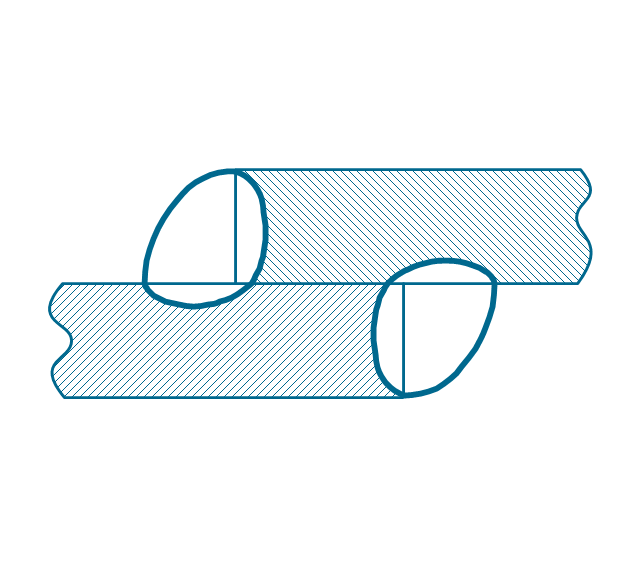
"A welding joint is a point or edge where two or more pieces of metal or plastic are joined together. They are formed by welding two or more workpieces (metal or plastic) according to a particular geometry. Five types of joints referred to by the American Welding Society: butt, corner, edge, lap, and tee. These configurations may have various configurations at the joint where actual welding can occur." [Welding joint. Wikipedia]
The engineering drawing example "Welded joints types" was created using the ConceptDraw PRO diagramming and vector drawing software extended with the Mechanical Engineering solution from the Engineering area of ConceptDraw Solution Park.
Welding joints
Welding joints, tee weld, mechanical weld, butt weld, bilateral lap weld, angular weld,
"A welding joint is a point or edge where two or more pieces of metal or plastic are joined together. They are formed by welding two or more workpieces (metal or plastic) according to a particular geometry. Five types of joints referred to by the American Welding Society: butt, corner, edge, lap, and tee. These configurations may have various configurations at the joint where actual welding can occur." [Welding joint. Wikipedia]
This engineering drawing example was redesigned using the ConceptDraw PRO diagramming and vector drawing software from the Wikimedia Commons file: Common joint types.png.
[commons.wikimedia.org/ wiki/ File:Common_ joint_ types.png]
This file is licensed under the Creative Commons Attribution-Share Alike 3.0 Unported license.
[creativecommons.org/ licenses/ by-sa/ 3.0/ deed.en]
The engineering drawing example "Common joint types" is included in the Mechanical Engineering solution from the Engineering area of ConceptDraw Solution Park.
Welding joint types
Welding joint types, square butt joint, single V preparation joint, lap joint, T-joint,

Entity Relationship Diagram Software for Mac

Great part of modern approaches to the database design are based on the use of different versions of ER-models. The important feature of entity-relationship model is that it can be visually represented as a graphical diagram. ER-models and Entity Relationship Diagrams are so popular due to the simplicity and the presentation clarity. The conceptual basis led to their widespread use in CASE-systems, which support automatic design of relational databases. The typical concepts for ER-models are entity, relation and attribute. Relation is a graphically represented association between two entities, that establishes certain rules and all instances of the linked entity types are subject to these rules. In common ER-model this association is always binary. For representing entity-relationship elements, there are used Crow’s foot and Chen notations. ConceptDraw DIAGRAM is a famous Entity Relationship Diagram software for Mac OSX which gives the ability to describe visually the databases with Chen’s and Crow’s Foot notation icons from Entity-Relationship Diagram (ERD) solution.

Process and Instrumentation Diagram

If you need create a Process and Instrumentation Diagram, it is convenient to design it in ConceptDraw DIAGRAM software which offers powerful Chemical and Process Engineering Solution from the Industrial Engineering Area.

Technical Drawing Software

Technical drawing or draft is a form of specialized graphic communication, exchange of ideas in industry and engineering. It is a visual representation of object with indication of dimensions and used material, constructed with maintaining the proportions between its parts. Technical drawings are constructed by architects, technologists, engineers, designers, drafters, and other technical professionals according to defined rules, specifications, internationally accepted standards and standardized notations allowing to make unambiguous, clear and understandable technical drawings. ConceptDraw DIAGRAM extended with Electrical Engineering solution, Mechanical Engineering solution, Chemical and Process Engineering solution from Industrial Engineering Area of ConceptDraw Solution Park is ideal technical drawing software. Its powerful drawing tools, predesigned vector objects, templates, samples are helpful for creation all kinds of Technical Drawings and Technical Diagrams, Electrical and Mechanical Schematics, Circuit and Wiring Diagrams, Structural Drawings, and many other.

Electrical Symbols — Thermo

A thermocouple is an electrical device consisting of two different conductors forming electrical junctions at differing temperatures. A thermocouple produces a temperature-dependent voltage as a result of the thermoelectric effect, and this voltage can be interpreted to measure temperature. Thermocouples are a widely used type of temperature sensor. 26 libraries of the Electrical Engineering Solution of ConceptDraw DIAGRAM make your electrical diagramming simple, efficient, and effective. You can simply and quickly drop the ready-to-use objects from libraries into your document to create the electrical diagram.

Selecting & Creating Flowcharts

ConceptDraw Flowcharts visualize a process or algorithm of program as step/operation blocks of various shapes connected with arrowed lines showed the process flow direction. They are used to visualize business or technical processes and software algorithms.

The Best Drawing Program for Mac

ConceptDraw DIAGRAM is the professional business graphic software for drawing diagrams and charts with great visual appeal on Mac OS X.

Model Based Systems Engineering

ConceptDraw DIAGRAM is a professional diagramming and vector drawing software. Now, enhanced with SysML Solution from the Software Development Area of ConceptDraw Solution Park, ConceptDraw DIAGRAM became an ideal software for model based systems engineering (MBSE).

systems engineering, sysml SYSML

systems engineering, sysml
In order to make a SysML-related drawing, the ConceptDraw DIAGRAM charting and drawing software can be used. Also, the SysML solution can be found as an extension to the ConceptDraw DIAGRAM application, enabling all those with systems engineering background to use the offered tools for creating the needed systems process models in order to use in the professional documentation for either distribution or analysis. Offering the vector stencil libraries full of the icons that may relate to each of the 9 official diagrams used in SysML, the SysML solution is useful for many system engineers.

user interface design examples, gui software, graphical user interface examples, user interface examples macOS User Interface

user interface design examples, gui software, graphical user interface examples, user interface examples
macOS User Interface solution extends the ConceptDraw DIAGRAM functionality with powerful GUI software graphic design features and tools. It provides an extensive range of multifarious macOS Sierra user interface design examples, samples and templates, and wide variety of libraries, containing a lot of pre-designed vector objects of Mac Apps icons, buttons, dialogs, menu bars, indicators, pointers, controls, toolbars, menus, and other elements for fast and simple designing high standard user interfaces of any complexity for new macOS Sierra.

Audio Connectors

Audio connectors are electrical connectors designed and used for audio frequencies. ConceptDraw DIAGRAM diagramming and vector drawing software extended with Audio and Video Connectors Solution from the Industrial Engineering Area is the best for drawing various audio schematics with detailed illustration the audio connectors.