 ATM UML Diagrams
The ATM UML Diagrams solution lets you create ATM solutions and UML examples. Use ConceptDraw DIAGRAM as a UML diagram creator to visualize a banking system.
HelpDesk
How to Create a Bank ATM Use Case Diagram

IDEF0 Diagram

UML Deployment Diagram Example - ATM System UML diagrams

Bank UML Diagram

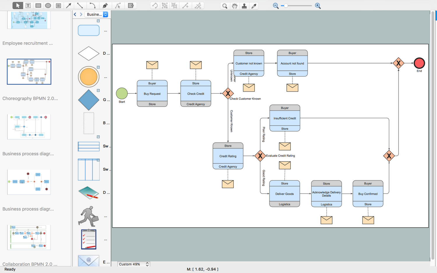
Business Process Modeling Tools
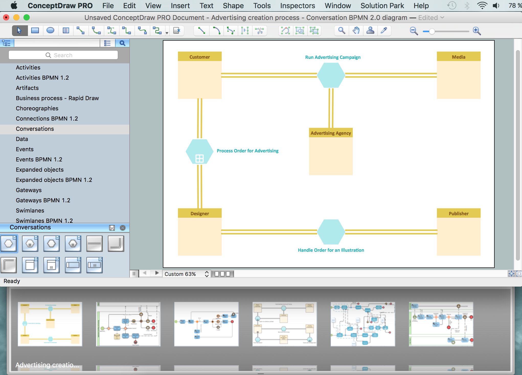
Business Process Modeling Software for Mac
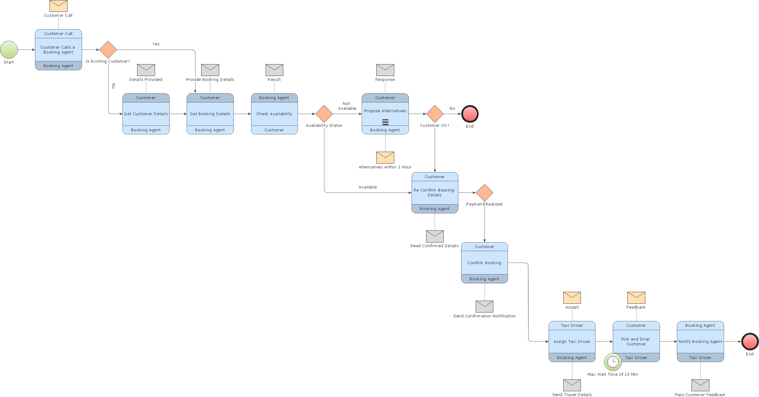
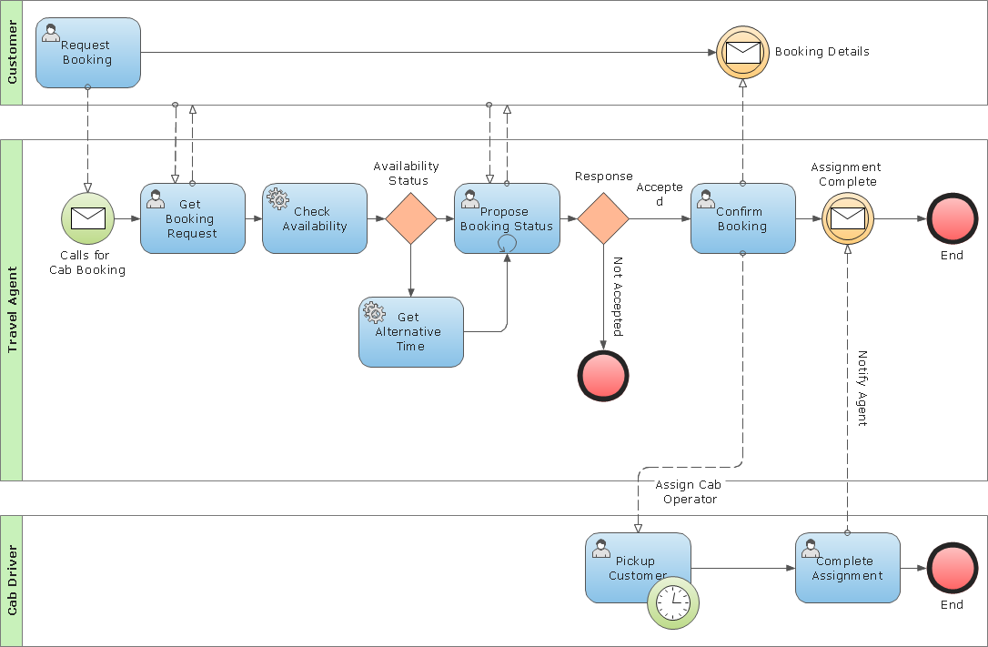
Business Process Modeling Notation
UML Software

Business Process Modeling Notation Template
- Software Process Models For Atm
- Business Process Diagrams | Process Of Atm Machine Process ...
- Fsm State Machine Model Of An Atm System
- ATM UML Diagrams | Business Process Diagrams | Social Media ...
- ATM UML Diagrams | Business Process Diagrams | Business ...
- Drwa A Sample Object Model Of Atm Machine
- UML activity diagram - Cash withdrawal from ATM | Business ...
- ATM UML Diagrams | BPMN 2.0 | BPMN | Withdraw Money Of Atm ...
- Event-driven Process Chain Diagrams | ATM UML Diagrams ...
- UML activity diagram - Cash withdrawal from ATM | ATM UML ...