Process Flow Diagram Symbols
Chemical and Process Engineering Solution from the Engineering Area of ConceptDraw Solution Park is a unique tool which contains variety of predesigned process flow diagram symbols for easy creating various Chemical and Process Flow Diagrams in ConceptDraw PRO.
 Mechanical Engineering
This solution extends ConceptDraw PRO v.9 mechanical drawing software (or later) with samples of mechanical drawing symbols, templates and libraries of design elements, for help when drafting mechanical engineering drawings, or parts, assembly, pneumatic,
 Chemical and Process Engineering
This chemical engineering solution extends ConceptDraw PRO v.9.5 (or later) with process flow diagram symbols, samples, process diagrams templates and libraries of design elements for creating process and instrumentation diagrams, block flow diagrams (BFD
Mechanical Engineering
ConceptDraw PRO is the best diagramming and vector drawing software. Now, enhanced with Mechanical Engineering solution from the Engineering area of ConceptDraw Solution Park it became ideal for creating: Technical Mechanical Drawings, Mechanical Engineering Diagrams, Pneumatic Schematics, Hydraulic Schemes, etc.Chemical Engineering
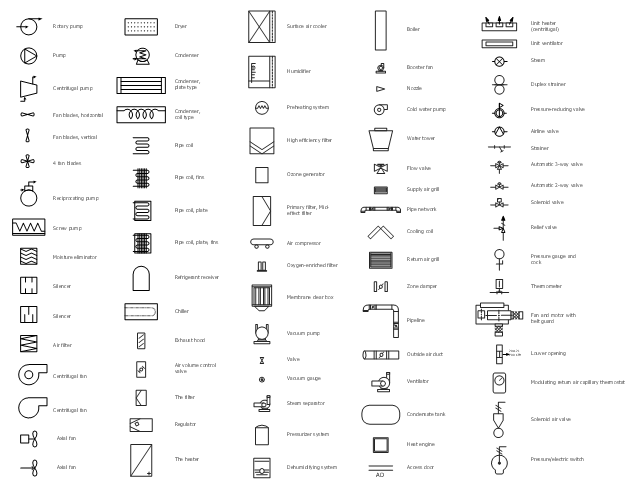
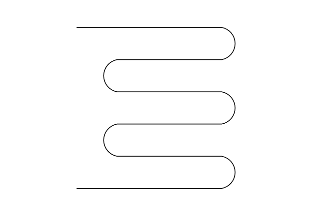
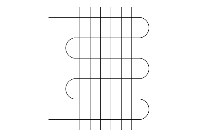
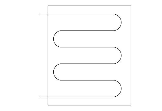
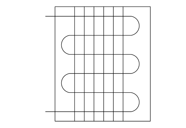
ConceptDraw PRO is a powerful diagramming and vector drawing software. Extended with Chemical and Process Engineering Solution from the Engineering Area of ConceptDraw Solution Park, it became the best Chemical Engineering software.The vector stencils library "HVAC equipment" contains 26 symbols of HVAC equipment as pumps, fans, condensers, pipe coils, silencers, etc.
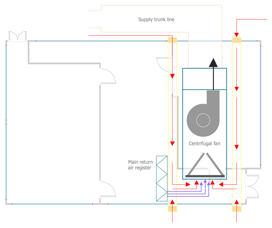
Use the design elements library "HVAC equipment" for drawing the HVAC system diagrams, heating, ventilation, air conditioning, refrigeration, automated building control and environmental control system layout floor plans using the ConceptDraw PRO diagramming and vector drawing software.
"HVAC (heating, ventilation, and air conditioning) is the technology of indoor and vehicular environmental comfort. HVAC system design is a subdiscipline of mechanical engineering, based on the principles of thermodynamics, fluid mechanics, and heat transfer. Refrigeration is sometimes added to the field's abbreviation as HVAC&R or HVACR, or ventilating is dropped as in HACR (such as the designation of HACR-rated circuit breakers).
HVAC is important in the design of medium to large industrial and office buildings such as skyscrapers and in marine environments such as aquariums, where safe and healthy building conditions are regulated with respect to temperature and humidity, using fresh air from outdoors." [HVAC. Wikipedia]
The shapes library "HVAC equipment" is contained in the HVAC Plans solution from the Building Plans area of ConceptDraw Solution Park.
The vector stencils library "HVAC equipment" contains 26 symbols of HVAC equipment. Use it for drawing HVAC system diagrams, heating, ventilation, air conditioning, refrigeration, automated building control and environmental control system layout floor plans in the ConceptDraw PRO diagramming and vector drawing software extended with the HVAC Plans solution from the Building Plans area of ConceptDraw Solution Park.
HVAC Business Plan
Long time you have looked for the convenient and helpful software for drawing HVAC Business Plan? Now ConceptDraw PRO diagramming and vector drawing software offers you the HVAC Plans Solution from the Building Plans Area that will help you create any desired HVAC Business Plan.This example engineering drawing showing the hydraulic directional control valve usage with floating motor and pressure compensated pump is redesigned using the ConceptDraw PRO diagramming and vector drawing software from the Wikimedia Commons file: DCV 17.jpg.
[commons.wikimedia.org/ wiki/ File:DCV_ 17.jpg]
This file is licensed under the Creative Commons Attribution-Share Alike 3.0 Unported license.
[creativecommons.org/ licenses/ by-sa/ 3.0/ deed.en]
"Directional control valves are one of the most fundamental parts in hydraulic machinery as well and pneumatic machinery. They allow fluid flow into different paths from one or more sources. They usually consist of a spool inside a cylinder which is mechanically or electrically controlled. The movement of the spool restricts or permits the flow, thus it controls the fluid flow. ...
The spool (sliding type) consists of lands and grooves.The lands block oil flow through the valve body. The grooves allow oil or gas to flow around the spool and through the valve body. There are two fundamental positions of directional control valve namely normal position where valve returns on removal of actuating force and other is working position which is position of a valve when actuating force is applied. There is another class of valves with 3 or more position that can be spring centered with 2 working position and a normal position. ...
Directional control valves can be classified according to:
(1) number of ports;
(2) number of positions;
(3) actuating methods;
(4) type of spool." [Directional control valve. Wikipedia]
The fluid power equipment drawing example "Directional control valve" is included in the Mechanical Engineering solution from the Engineering area of ConceptDraw Solution Park.
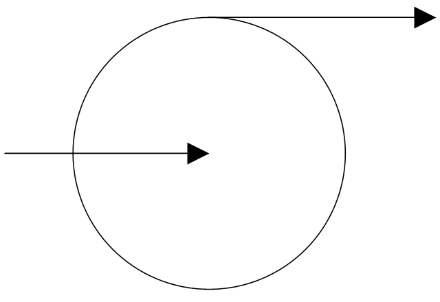
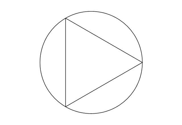
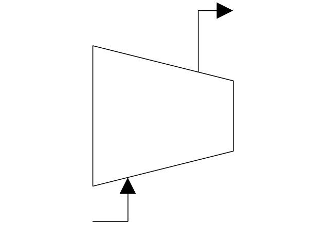
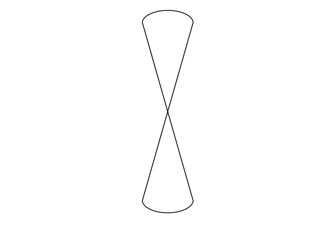
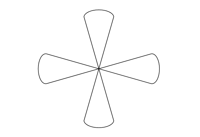
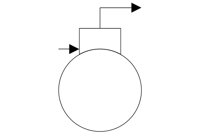
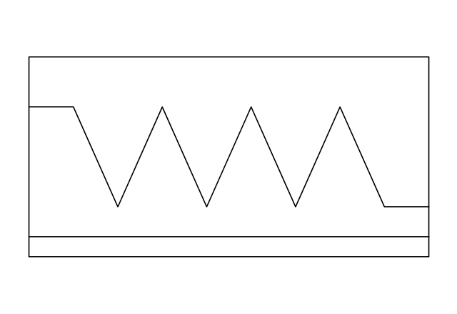
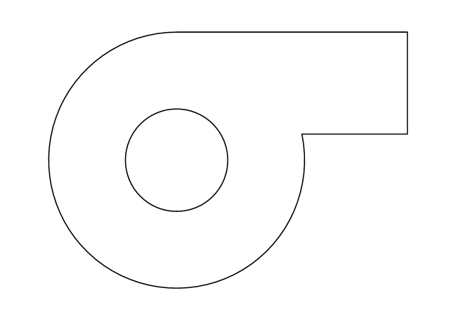
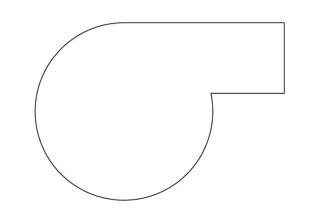
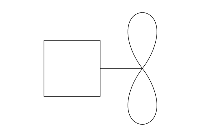
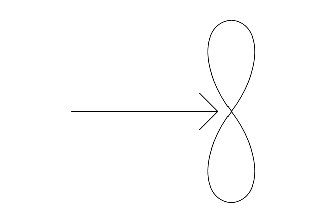
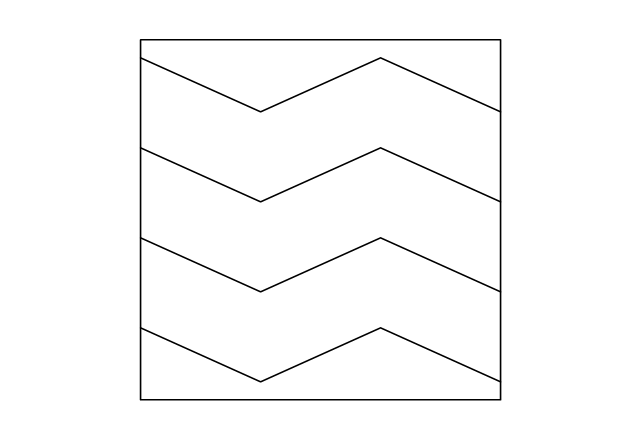
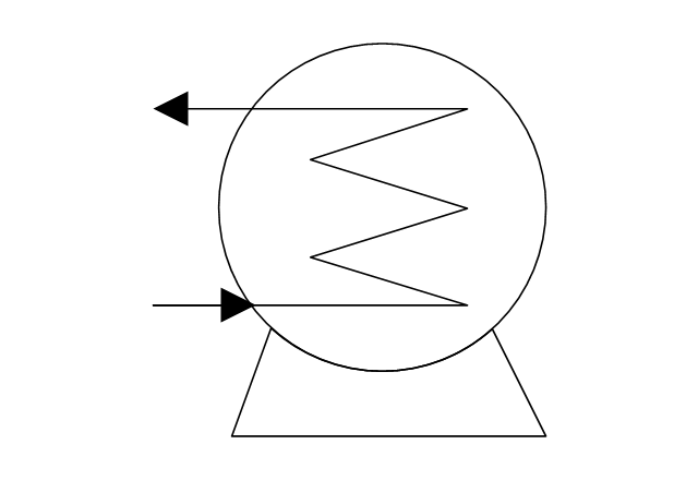
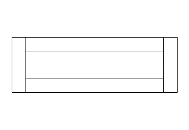
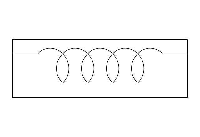
The vector stencils library "Fluid power equipment" contains 113 symbols of hydraulic and pneumatic equipment including pumps, motors, air compressors, cylinders, meters, gauges, and actuators.
Use it to design fluid power and hydraulic control systems in the ConceptDraw PRO diagramming and vector drawing software extended with the Mechanical Engineering solution from the Engineering area of ConceptDraw Solution Park.
www.conceptdraw.com/ solution-park/ engineering-mechanical
Use it to design fluid power and hydraulic control systems in the ConceptDraw PRO diagramming and vector drawing software extended with the Mechanical Engineering solution from the Engineering area of ConceptDraw Solution Park.
www.conceptdraw.com/ solution-park/ engineering-mechanical
- Mechanical Drawing Symbols | Hydraulic pumps and motors ...
- Schematic Diagram Of Bag Filter
- Mechanical Drawing Symbols | Process Flow Diagram Symbols ...
- Mechanical Drawing Symbols | Design elements - Fluid power ...
- Electrical Drawing Software and Electrical Symbols | Chemical ...
- Directional control valve | Hydraulic Filter Schematic Diagram
- Filter Schematic Symbol
- Hydraulic schematic | Hydraulic circuits | Mechanical Drawing ...
- Electrical Symbols , Electrical Diagram Symbols | Chemical ...
- Mechanical Drawing Symbols | Mechanical Engineering | Technical ...
- Symbol Of Motor Pump Valve In Line Diagram
- Mechanical Drawing Symbols | Process Flow Diagram Symbols ...
- Hydraulic Circuit Strainer Symbol
- Filter Press Symbol
- How to Use Filters | Presentation Exchange | Electrical Symbols ...
- Electrical Symbols , Electrical Diagram Symbols | Chemical ...
- Electrical Drawing Software and Electrical Symbols | Industrial ...
- Horizontal Filter Diagram Symbol
- The Symbol For Rotary Filter In Chemical Engineering
- Fluid power equipment - Vector stencils library | Electrical Drawing ...




,-pneumatic-fluid-power-equipment---vector-stencils-library.png--diagram-flowchart-example.png)
,-hydraulic-fluid-power-equipment---vector-stencils-library.png--diagram-flowchart-example.png)


-fluid-power-equipment---vector-stencils-library.png--diagram-flowchart-example.png)
-fluid-power-equipment---vector-stencils-library.png--diagram-flowchart-example.png)
-fluid-power-equipment---vector-stencils-library.png--diagram-flowchart-example.png)
-fluid-power-equipment---vector-stencils-library.png--diagram-flowchart-example.png)


