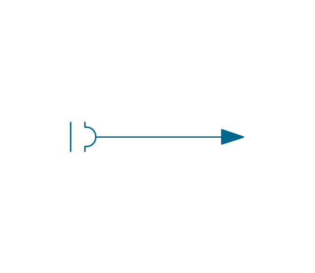
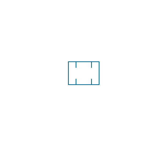
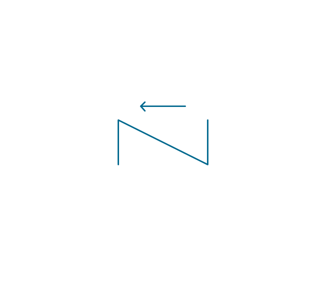
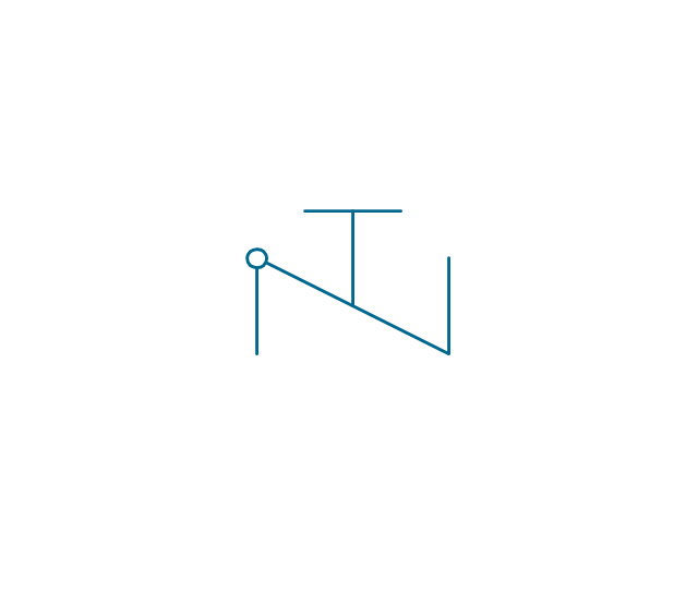
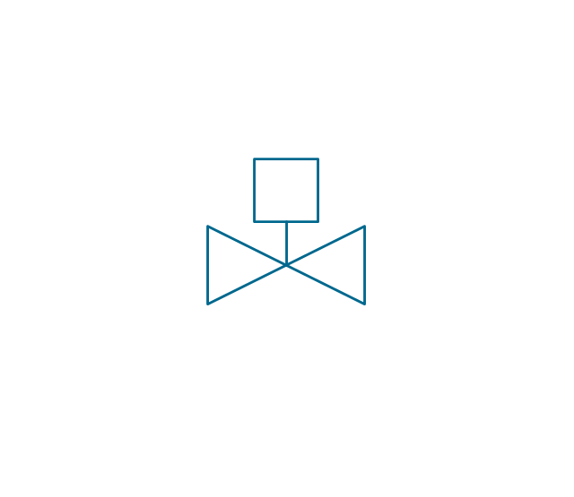
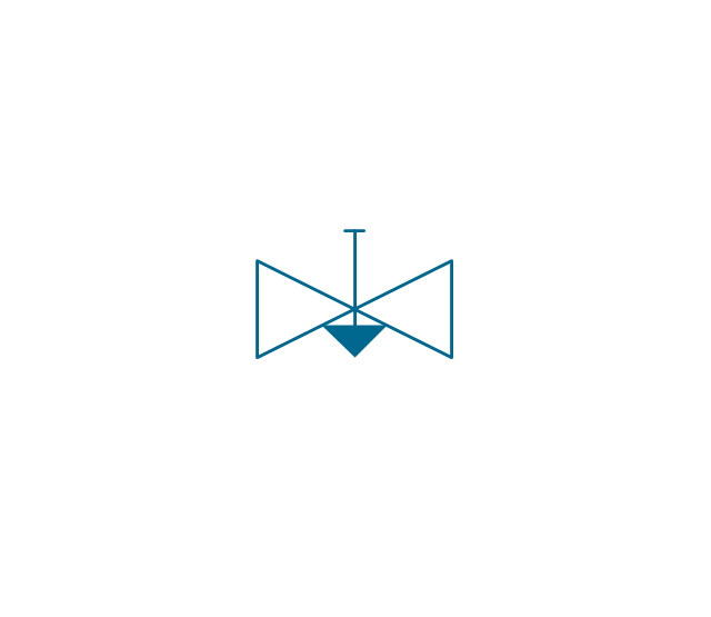
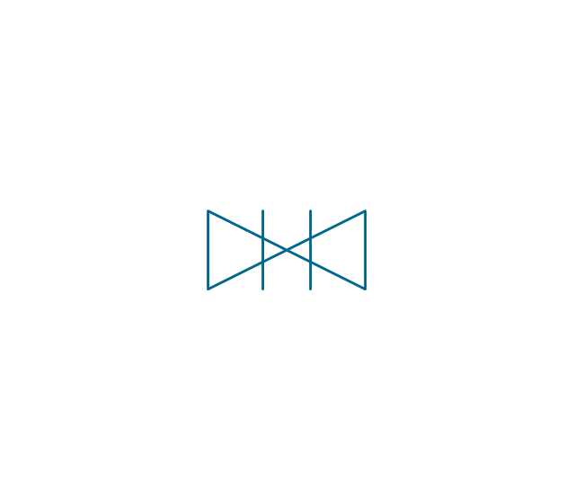
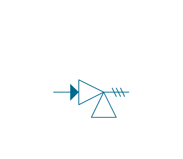
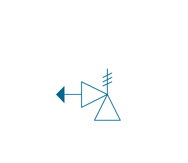
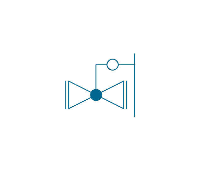
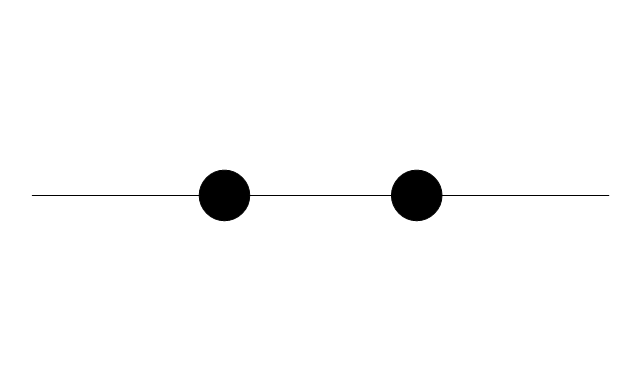
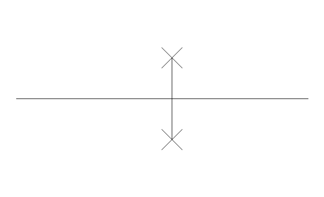
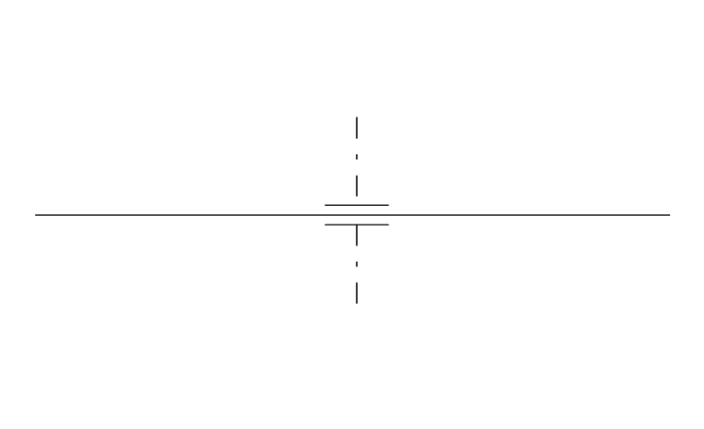
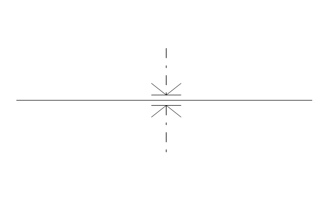
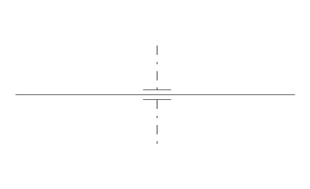
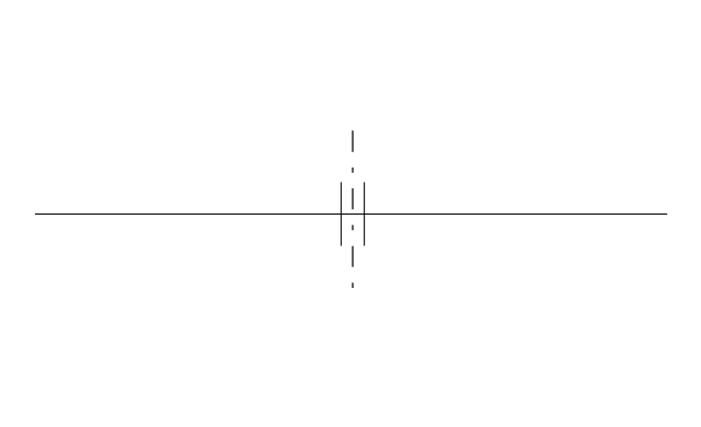
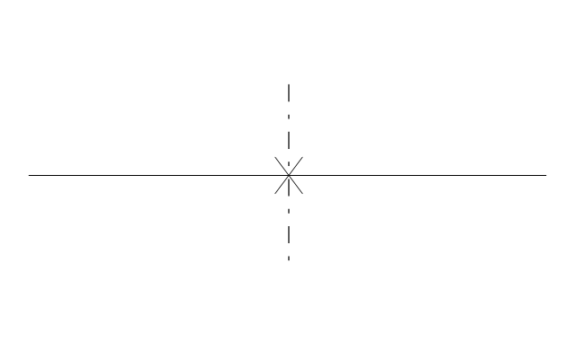
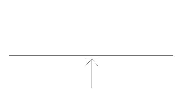
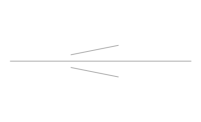
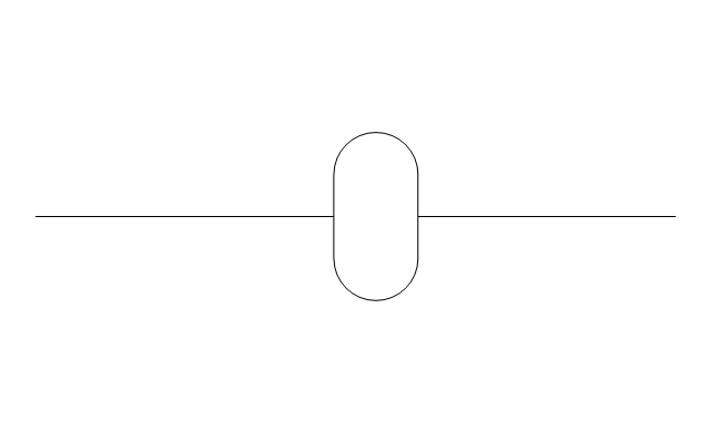
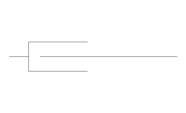
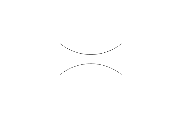
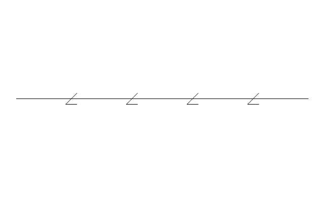
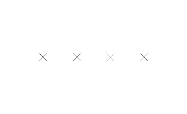
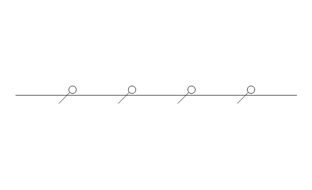
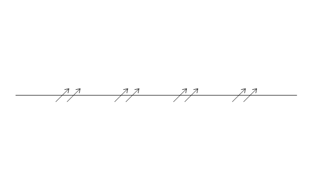
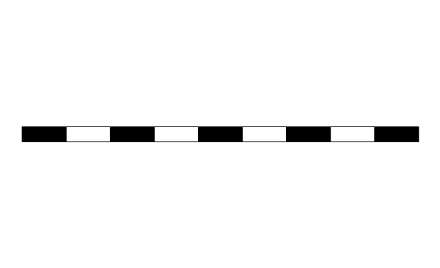
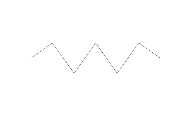
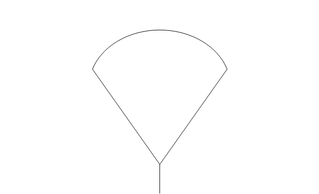
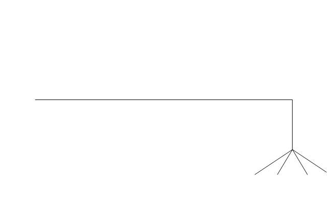
The vector stencils library "Pipes 2" contains 48 symbols of pipes. Use it for drawing plumbing and piping building plans, schematic diagrams, blueprints, or technical drawings of waste water disposal systems, hot and cold water supply systems in the ConceptDraw PRO diagramming and vector drawing software extended with the Plumbing and Piping Plans solution from the Building Plans area of ConceptDraw Solution Park.
The vector stencils libraries "Pipes 1" and "Pipes 2" contain 28 and 48 pipe, tubing and fitting symbols, respectively.
"Pipe is hollow cylinder used to conduct or transfer fluids (liquids and gases) from one place to other place. The main difference between pipe and tube is the critical dimension used to describe the pipe size or the tube size. For pipe, internal diameter (ID) roughly corresponds to the nominal pipe size for standard wall thickness. For tube, the outer diameter (OD) closely corresponds to the tube size. In current European standards pipes and tubes are nowadays described as outside diameter by wall thickness. The three standard types of pipe ends used in the piping industriesare; Plain Ends (PE), Threaded Ends (TE) and Beveled Ends (BE). In the past, many types of material have been used in conveying water from one point to another. Masonry and wood were probably the first materials used. Plastics are the newest, and are now being used quite extensively." [Piping. Wikipedia]
Use the design elements libraries "Pipes 1" and "Pipes 2" for drawing plumbing and piping building plans, schematic diagrams, blueprints, or technical drawings of waste water disposal systems, hot and cold water supply systems using the ConceptDraw PRO diagramming and vector drawing software.
The shapes libraries "Pipes 1" and "Pipes 2" are contained in the Plumbing and Piping Plans solution from the Building Plans area of ConceptDraw Solution Park.
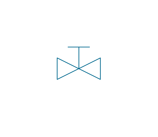
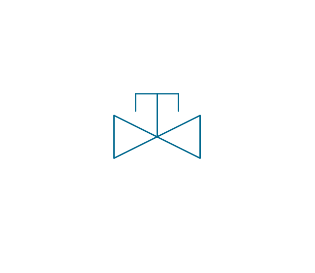
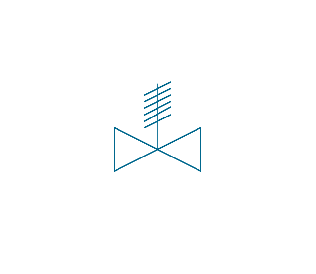
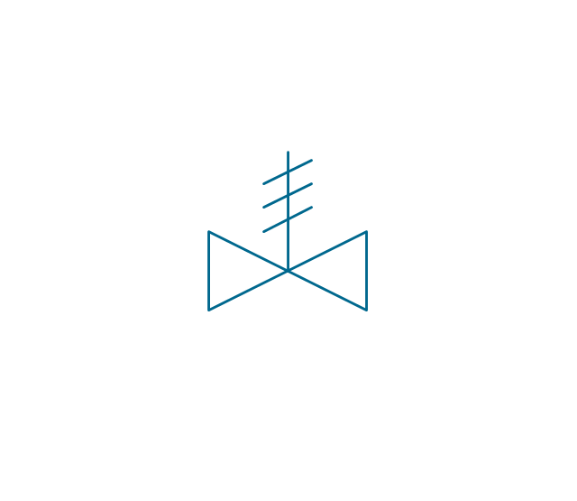
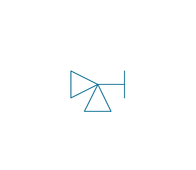
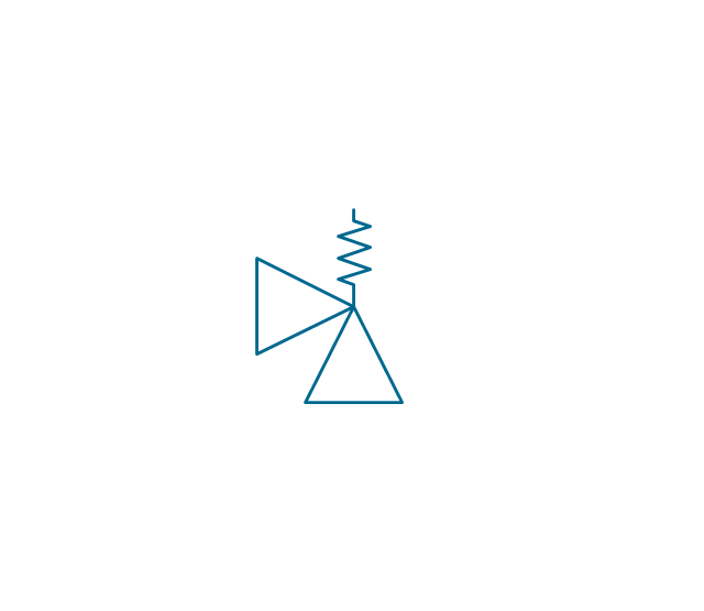
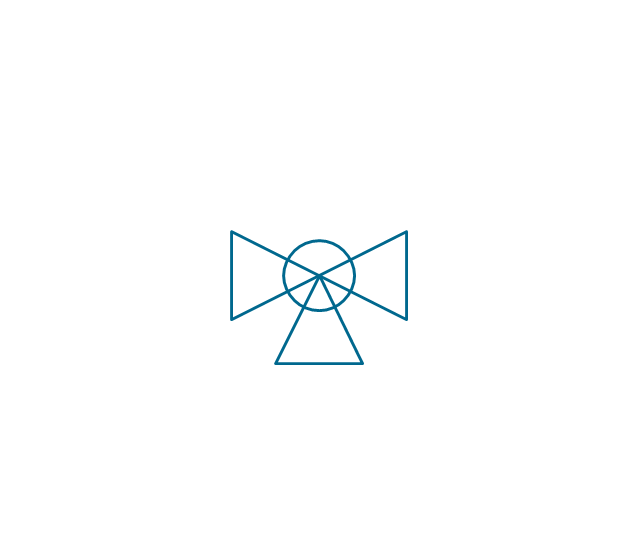
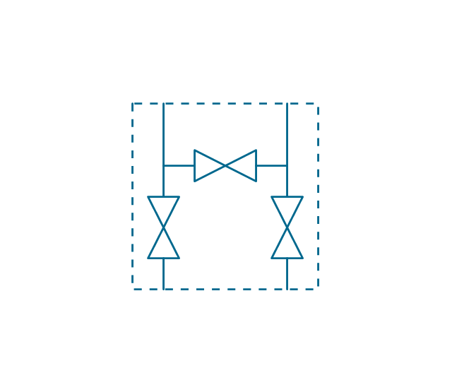
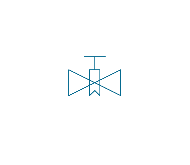
The vector stencils library "Valves and fittings" contains 104 symbols of valve components.
Use these icons for drawing industrial piping systems; process, vacuum, and fluids piping; hydraulics piping; air and gas piping; materials distribution; and liquid transfer systems in the ConceptDraw PRO software extended with the Chemical and Process Engineering solution from the Chemical and Process Engineering area of ConceptDraw Solution Park.
www.conceptdraw.com/ solution-park/ engineering-chemical-process
 Chemical and Process Engineering
This chemical engineering solution extends ConceptDraw PRO v.9.5 (or later) with process flow diagram symbols, samples, process diagrams templates and libraries of design elements for creating process and instrumentation diagrams, block flow diagrams (BFD
- Interior Design Piping Plan - Design Elements | Symbol Of ...
- Pipe Fitter Bell And Spigot Symbol
- Silencer Symbol In Pipe Fitting
- Pipeline Anchor Support Drafting Symbol
- Piping Symbols And Fittings
- Symbol Of T Reducer
- Reducer Pipe Icon Png
- Valves and fittings - Vector stencils library | Interior Design Piping ...
- Flame Arrestor On Gas Piping Symbol
- Valves and fittings - Vector stencils library | Interior Design Piping ...
- Interior Design Piping Plan Design Element | Design elements ...
- Pipe Coupling Socket Weld Symbol
- Mechanical Pipe Symbol
- Design elements - Pipes (part 2) | ABC - Vector stencils library ...
- Mechanical Drawing Symbols | Mechanical Engineering | Pipes 2 ...
- Interior Design Piping Plan - Design Elements | Pipes 2 - Vector ...
- Pipe Welding Drawing Symbols
- Symbol Of Pipe Joint
- Interior Design Piping Plan - Design Elements | Welding symbols ...





.png--diagram-flowchart-example.png)
