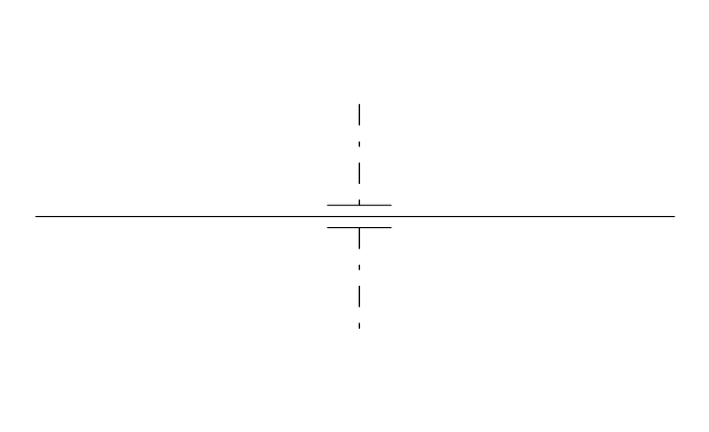
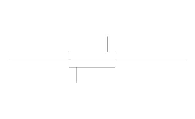
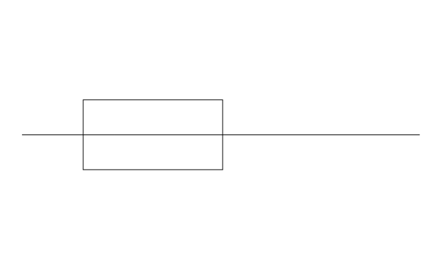
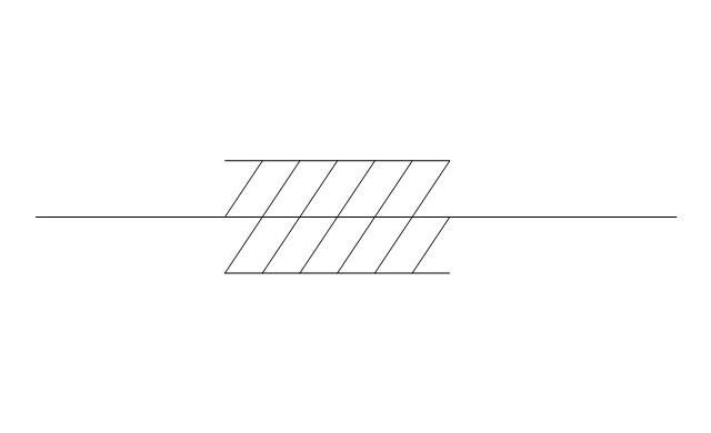
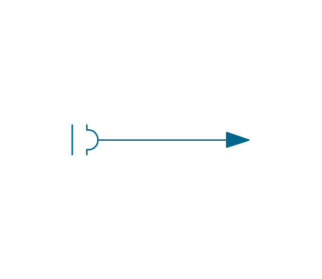
The vector stencils library "Pipes 2" contains 48 symbols of pipes. Use it for drawing plumbing and piping building plans, schematic diagrams, blueprints, or technical drawings of waste water disposal systems, hot and cold water supply systems in the ConceptDraw PRO diagramming and vector drawing software extended with the Plumbing and Piping Plans solution from the Building Plans area of ConceptDraw Solution Park.
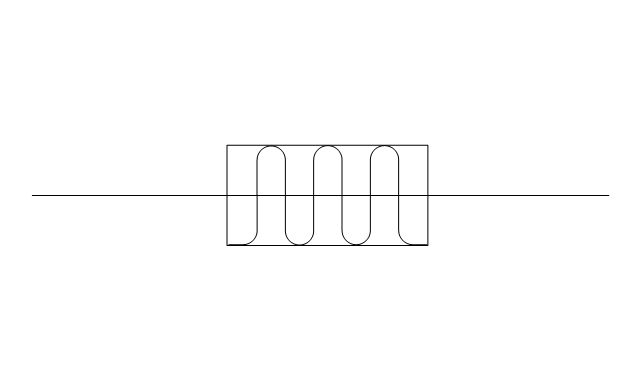
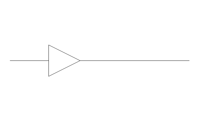
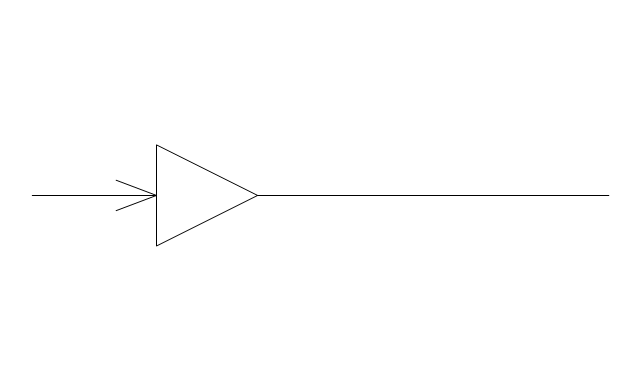
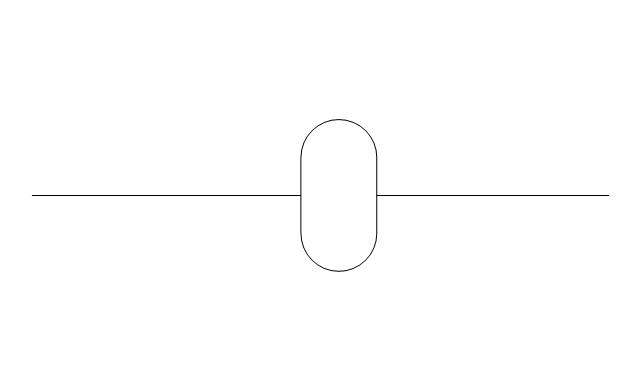
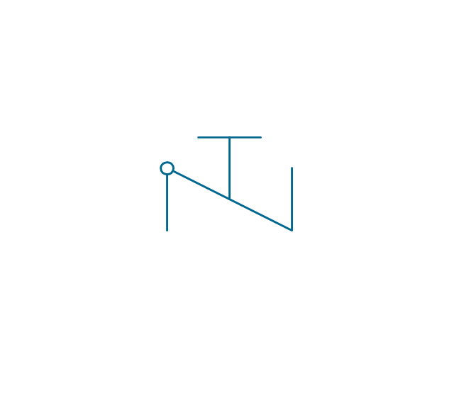
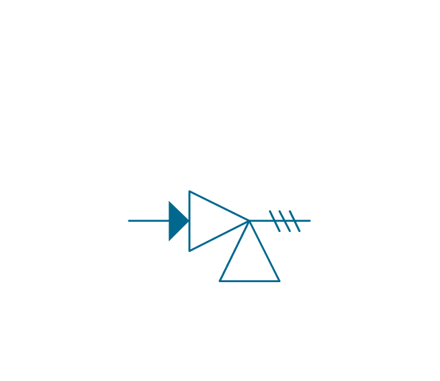
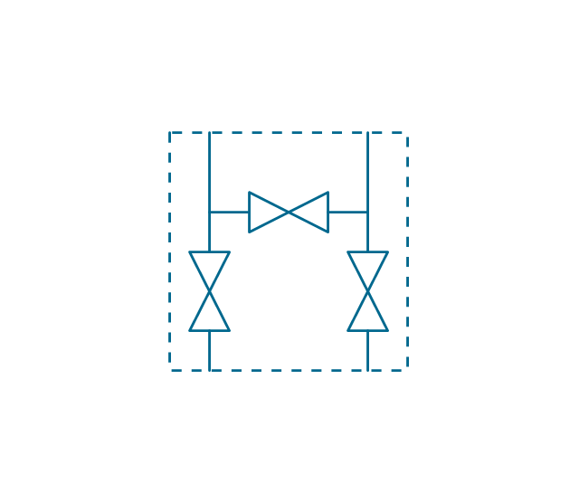
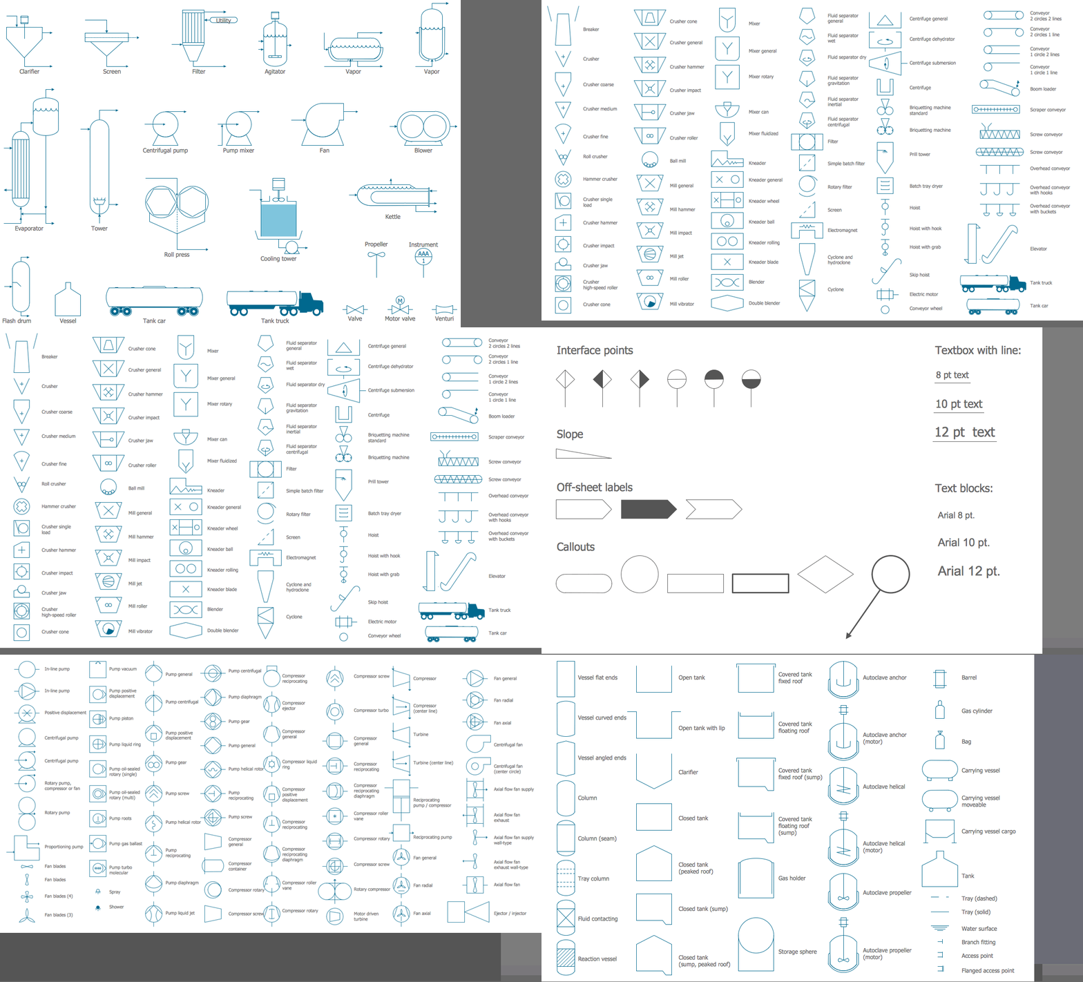
The vector stencils library "Valves and fittings" contains 104 symbols of valve components.
Use these icons for drawing industrial piping systems; process, vacuum, and fluids piping; hydraulics piping; air and gas piping; materials distribution; and liquid transfer systems in the ConceptDraw PRO software extended with the Chemical and Process Engineering solution from the Chemical and Process Engineering area of ConceptDraw Solution Park.
www.conceptdraw.com/ solution-park/ engineering-chemical-process
P&ID Drawing Program
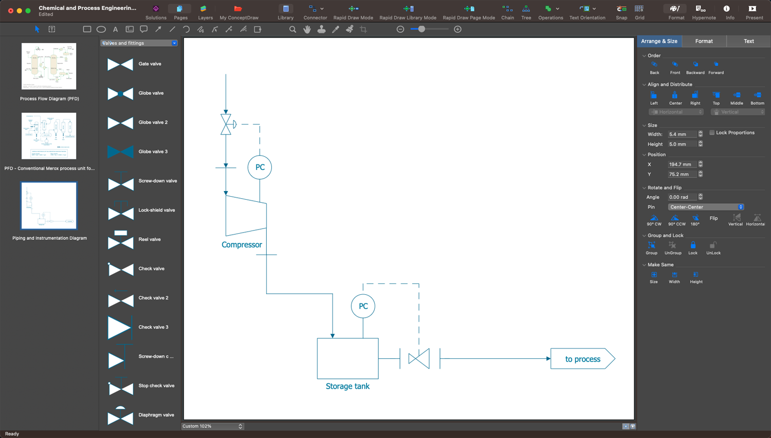
ConceptDraw DIAGRAM with included Chemical and Process Engineering solution is a simple and convenient way to create Piping and Instrumentation Diagrams at the stage of your plant design, planning, construction, and maintenance. It is a streamlined P&ID drawing program for all technical specialists, electrical, mechanical, and process engineers, piping designers, technical developers, and other stakeholders. Accurate design elements help to show the physical sequence of equipment and systems, how the system components are connected with piping, maintain and modify your processes, keep track of basic operational details, and control plant operation easily.Interior Design. Piping Plan — Design Elements
The pipe laying and setting the plumbing system at new apartment or home, or replacing the worn plumbing begins from the choice of materials, sizes of pipes and creation the plan. When developing a piping system, the engineer should take into account many aspects, such as advantages and disadvantages of different pipes materials, the temperature changes (freezing or thermal expansion) that effect on pipes. The most commonly used are steel pipes which have passed the test of time, but they are difficult for assembling and prone to corrosion, plastic (polypropylene) pipes that are characterized by low weight and price, ease of installation and durability, and also PEX-AL-PEX pipes. Numerous libraries with ready-to-use design elements of pipes, valves and other plumbing and piping equipment included to Plumbing and Piping Plans solution for ConceptDraw DIAGRAM help easy design Piping and Plumbing interior design plans, blueprints, schematic diagrams, technical drawings of waste water disposal systems, hot and cold water supply systems.P&ID Diagram Software
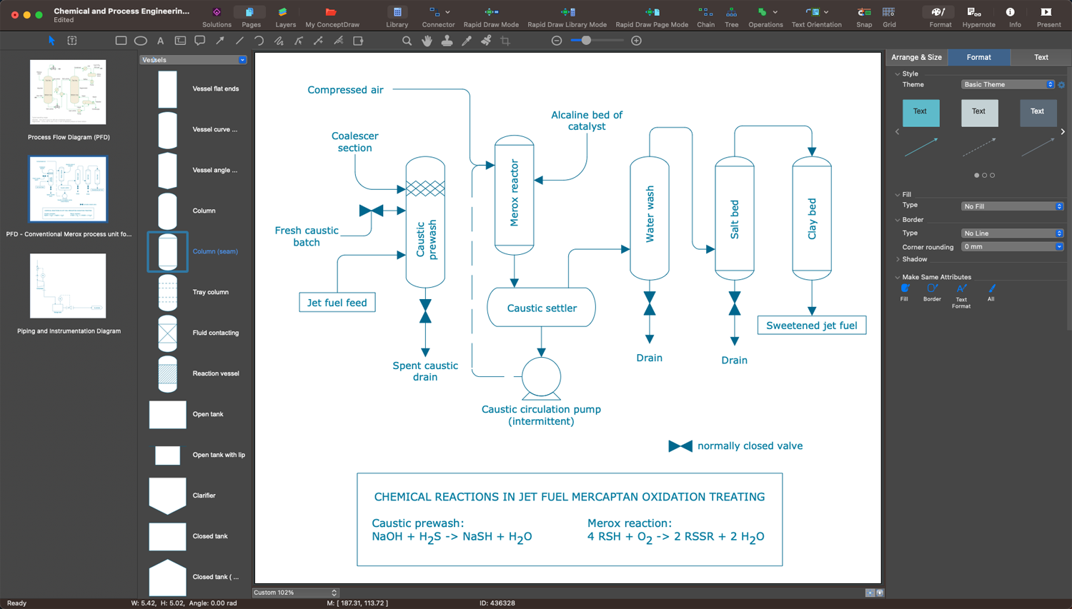
Creating a P&ID diagram is a complicated process, but professional drawing software makes easier the drawing process. ConceptDraw DIAGRAM with Chemical and Process Engineering solution is excellent P&ID diagram software for both beginners and professional engineers to create P&ID and save time on documentation. Create unique content for industrial, business, and individual purposes easily with amazing features and a significant number of pre-made symbols and icons. Show the connectivity in a control system and process sequence.P&ID Drawing Tool
ConceptDraw DIAGRAM enhanced with Chemical and Process Engineering solution is a powerful engineering system design software and handy P&ID drawing tool useful for all engineers. Use it to develop a plant or industrial facility project, design manufacturing processes, visualize the physical sequence of the equipment. Design efficiently your processing plans, create professional-looking P&IDs, show the piping and associated parts of a physical process flow, and track the operation of a plant. The included samples are great examples and customizable templates are the best basis for your own diagrams no matter the complexity of your process or system.The vector stencils libraries "Pipes 1" and "Pipes 2" contain 28 and 48 pipe, tubing and fitting symbols, respectively.
"Pipe is hollow cylinder used to conduct or transfer fluids (liquids and gases) from one place to other place. The main difference between pipe and tube is the critical dimension used to describe the pipe size or the tube size. For pipe, internal diameter (ID) roughly corresponds to the nominal pipe size for standard wall thickness. For tube, the outer diameter (OD) closely corresponds to the tube size. In current European standards pipes and tubes are nowadays described as outside diameter by wall thickness. The three standard types of pipe ends used in the piping industriesare; Plain Ends (PE), Threaded Ends (TE) and Beveled Ends (BE). In the past, many types of material have been used in conveying water from one point to another. Masonry and wood were probably the first materials used. Plastics are the newest, and are now being used quite extensively." [Piping. Wikipedia]
Use the design elements libraries "Pipes 1" and "Pipes 2" for drawing plumbing and piping building plans, schematic diagrams, blueprints, or technical drawings of waste water disposal systems, hot and cold water supply systems using the ConceptDraw PRO diagramming and vector drawing software.
The shapes libraries "Pipes 1" and "Pipes 2" are contained in the Plumbing and Piping Plans solution from the Building Plans area of ConceptDraw Solution Park.
- Pipes 2 - Vector stencils library | Valves and fittings - Vector stencils ...
- Process Flow Diagram Symbols | Valves and fittings - Vector stencils ...
- Design elements - Pipes (part 1) | Socket Symbol Plumber Pipe Line
- Design elements - Pipes (part 2) | Chemical and Process Engineering
- Design elements - Fluid power valves | Valve Symbols
- Electrical Symbols — Terminals and Connectors | Pipes 2 - Vector ...
- Mechanical Drawing Symbols | Technical Drawing Software ...
- How to Draw a Chemical Process Flow Diagram | Chemical and ...
- Welding symbols | Mechanical Drawing Symbols | Design elements ...
- Process Flowchart | Hollow Pipe Symbol In Engineering Drawing













































































































































.png--diagram-flowchart-example.png)