 Cafe and Restaurant Floor Plans
Restaurants and cafes are popular places for recreation, relaxation, and are the scene for many impressions and memories, so their construction and design requires special attention. Restaurants must to be projected and constructed to be comfortable and e
 ConceptDraw Solution Park
ConceptDraw Solution Park collects graphic extensions, examples and learning materials
 Entity-Relationship Diagram (ERD)
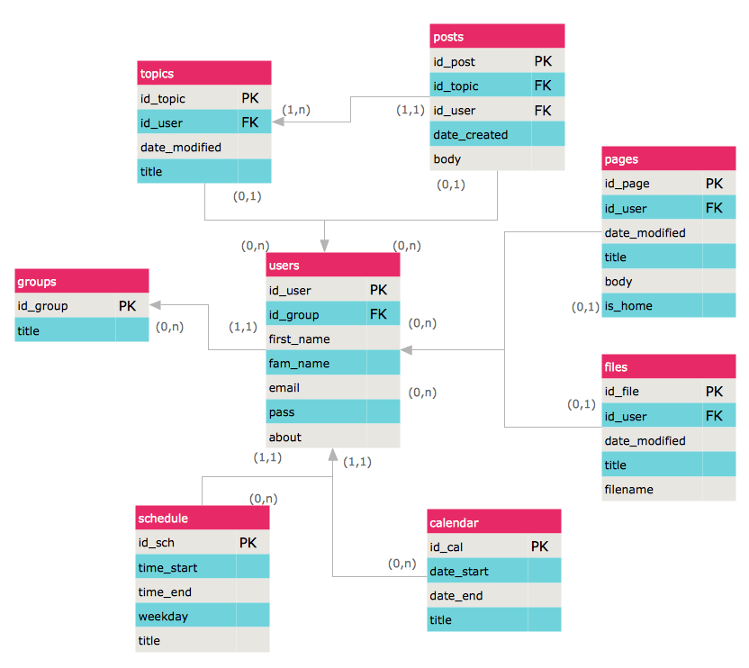
An Entity-Relationship Diagram (ERD) is a visual presentation of entities and relationships. That type of diagrams is often used in the semi-structured or unstructured data in databases and information systems. At first glance ERD is similar to a flowch
HelpDesk
How to Create an ERD Diagram
ERD (entity relationship diagram) is used to show the logical structure of databases. It represents the interrelationships between components of database (entities). Entity relationship diagrams are a widely used in software engineering. Using ERD software engineers can control the every aspect of database development. ER diagram can be used as guide for testing and communicating before the release of software product. ERD displays data as entities that are connected with connections that show the relationships between entities. There is some ERD notations used by data bases developers for representing the relationships between the data objects. ConceptDraw PRO and its ERD solution allow you to build ERD diagram of any notation.
 Network Layout Floor Plans
Network Layout Floor Plans solution extends ConceptDraw PRO software functionality with powerful tools for quick and efficient documentation the network equipment and displaying its location on the professionally designed Network Layout Floor Plans. Never before creation of Network Layout Floor Plans, Network Communication Plans, Network Topologies Plans and Network Topology Maps was not so easy, convenient and fast as with predesigned templates, samples, examples and comprehensive set of vector design elements included to the Network Layout Floor Plans solution. All listed types of plans will be a good support for the future correct cabling and installation of network equipment.
 Sales Flowcharts
The Sales Flowcharts solution lets you create and display sales process maps, sales process workflows, sales steps, the sales process, and anything else involving sales process management.
 Event-driven Process Chain Diagrams
Event-driven Process Chain (EPC) Diagram is a type of flowchart widely used for modeling in business engineering and reengineering, business process improvement, and analysis. EPC method was developed within the Architecture of Integrated Information Systems (ARIS) framework.
 Fishbone Diagrams
The Fishbone Diagrams solution extends ConceptDraw PRO v10 software with the ability to easily draw the Fishbone Diagrams (Ishikawa Diagrams) to clearly see the cause and effect analysis and also problem solving. The vector graphic diagrams produced using this solution can be used in whitepapers, presentations, datasheets, posters, and published technical material.
- Entity-Relationship Diagram (ERD) | ConceptDraw PRO ER ...
- Jacobson Use Cases Diagram | Entity-Relationship Diagram (ERD ...
- Entity-Relationship Diagram (ERD) | Cafe and Restaurant Floor Plan ...
- Cafe and Restaurant Floor Plan | Entity-Relationship Diagram (ERD ...
- Entity-Relationship Diagram (ERD) | ConceptDraw Solution Park ...
- Cafe and Restaurant Floor Plan | Entity-Relationship Diagram (ERD ...
- Restaurant Floor Plan Software | Entity-Relationship Diagram (ERD ...
- Entity-Relationship Diagram (ERD) | Use case restaurant model ...
- How To Create Restaurant Floor Plan in Minutes | Entity ...
- How To Create Restaurant Floor Plan in Minutes | Entity ...
- Data Flow Diagrams ( DFD ) | ConceptDraw Solution Park | Cafe and ...
- Engineering | How To Create Restaurant Floor Plan in Minutes ...
- How To Create Restaurant Floor Plan in Minutes | Entity ...
- Cafe and Restaurant Floor Plan | Entity Relationship Diagram ...
- Entity-Relationship Diagram (ERD) | Enterprise Architecture ...
- How To Create Restaurant Floor Plan in Minutes | Entity ...
- Active Directory Diagram | How To Create Restaurant Floor Plan in ...
- Entity-Relationship Diagram (ERD) | How to Create an ERD ...
- Entity-Relationship Diagram (ERD) | ConceptDraw Solution Park ...
