 Fault Tree Analysis Diagrams
This solution extends ConceptDraw PRO v9.5 or later with templates, fault tree analysis example, samples and a library of vector design elements for drawing FTA diagrams (or negative analytical trees), cause and effect diagrams and fault tree diagrams.
 Fishbone Diagrams
The Fishbone Diagrams solution extends ConceptDraw PRO v10 software with the ability to easily draw the Fishbone Diagrams (Ishikawa Diagrams) to clearly see the cause and effect analysis and also problem solving. The vector graphic diagrams produced using this solution can be used in whitepapers, presentations, datasheets, posters, and published technical material.
 Event-driven Process Chain Diagrams
Event-driven Process Chain (EPC) Diagram is a type of flowchart widely used for modeling in business engineering and reengineering, business process improvement, and analysis. EPC method was developed within the Architecture of Integrated Information Systems (ARIS) framework.
 SYSML
SYSML
The SysML solution helps to present diagrams using Systems Modeling Language; a perfect tool for system engineering.
 Fishbone Diagram
Fishbone Diagrams solution extends ConceptDraw PRO software with templates, samples and library of vector stencils for drawing the Ishikawa diagrams for cause and effect analysis.
HelpDesk
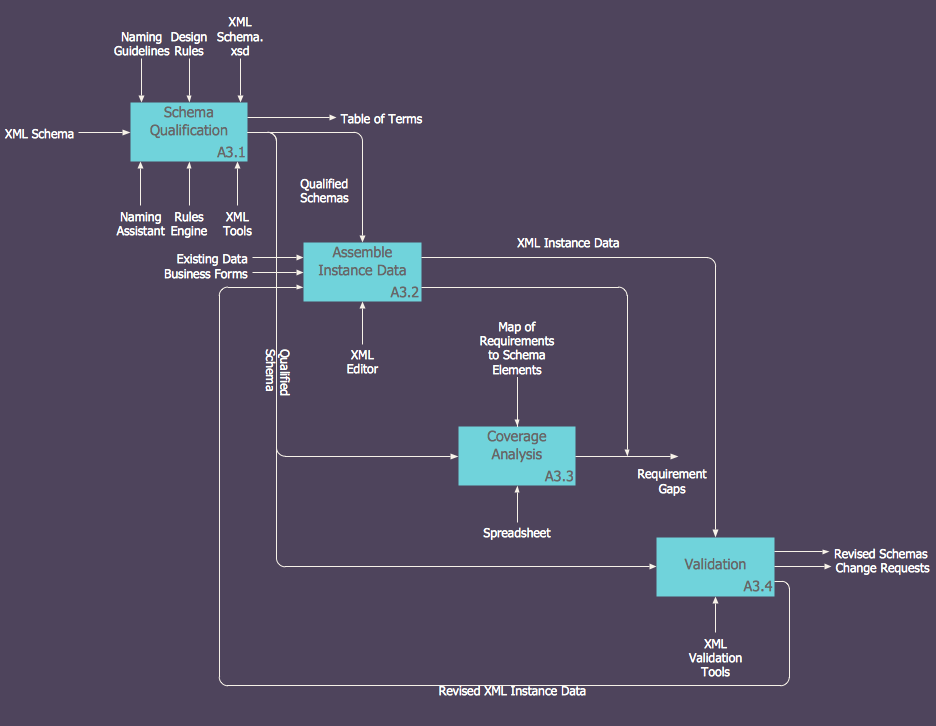
How to Create an IDEF0 Diagram for an Application Development
IDEF0 methods are intended to model the functions of a process, creating a graphical model that displays: what controls the function, who makes it, what resources are used and how they are connected with other functions. The IDEF0 tool is used to model the decisions, actions, and activities of a software system during the development process . IDEF0 diagram graphically depicts a model of a desired version of the application. ConceptDraw PRO allows you to create and communicate the IDEF0 diagrams of any complexity.- Uml Diagrams For Restaurant Management System Pdf
- Restaurant Management System Pdf
- Uml Class Diagram For A Restaurant Management System
- Draw Class Diagram Restaurant Management System Dowland Pdf
- Class Diagram Restaurant Pdf
- Class Diagram For Restaurant Management System Ppt
- Er Diagram For Restaurant Management System Pdf
- Class Diagram For Restaurant Management System
- Pdf Of Restaurant Management System
- Uml Class Diagram For Restaurant Management System
- Class Diagram Of Online Restaurant Management System Project
- Uml Diagrams Of Restaurant Management System
- Restaurent Management System Uml Duagrams
- Class Diagram For Trade Management System
- Restaurant Management System Uml Project
- Dfd Of Restaurant Management System Project
- Class Diagram For Restaurant System
- Gantt Chart For Restaurant Management System
- Restaurant Management System Uml Diagrams
- Restaurant Management System Project Dfd
