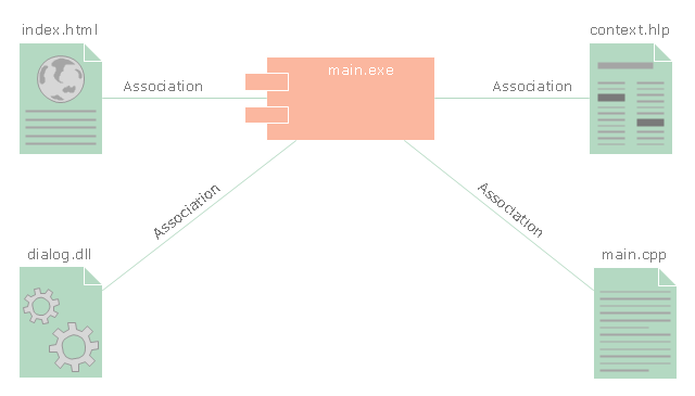
"In the Unified Modeling Language, a component diagram depicts how components are wired together to form larger components and or software systems. They are used to illustrate the structure of arbitrarily complex systems." [Component diagram. Wikipedia]
This UML component diagram example was created using the ConceptDraw PRO diagramming and vector drawing software extended with the Rapid UML solution from the Software Development area of ConceptDraw Solution Park.
This UML component diagram example was created using the ConceptDraw PRO diagramming and vector drawing software extended with the Rapid UML solution from the Software Development area of ConceptDraw Solution Park.
 Rapid UML
Rapid UML solution extends ConceptDraw PRO software with templates, samples and libraries of vector stencils for quick drawing the UML diagrams using Rapid Draw technology.
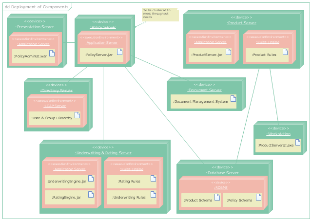
"A deployment diagram in the Unified Modeling Language models the physical deployment of artifacts on nodes. To describe a web site, for example, a deployment diagram would show what hardware components ("nodes") exist (e.g., a web server, an application server, and a database server), what software components ("artifacts") run on each node (e.g., web application, database), and how the different pieces are connected (e.g. JDBC, REST, RMI)." [Deployment diagram. Wikipedia]
This UML deployment diagram example was created using the ConceptDraw PRO diagramming and vector drawing software extended with the Rapid UML solution from the Software Development area of ConceptDraw Solution Park.
This UML deployment diagram example was created using the ConceptDraw PRO diagramming and vector drawing software extended with the Rapid UML solution from the Software Development area of ConceptDraw Solution Park.
 Cross-Functional Flowcharts
Cross-functional flowcharts are powerful and useful tool for visualizing and analyzing complex business processes which requires involvement of multiple people, teams or even departments. They let clearly represent a sequence of the process steps, the order of operations, relationships between processes and responsible functional units (such as departments or positions).
- UML Deployment Diagram | Diagramming Software for Design UML ...
- Diagramming Software for Design UML Collaboration Diagrams ...
- UML Component Diagram
- UML Use Case Diagrams | UML Component Diagram ...
- UML Deployment Diagram
- UML Deployment Diagram | UML Component Diagram ...
- UML Component Diagram | Diagramming Software for Design UML ...
- UML Component Diagram | Draw Network Diagram based on ...
- UML deployment diagram example | UML Class Diagrams ...
- UML Component Diagram
- UML Component Diagram | Rapid UML | UML Diagrams with ...
- UML Deployment Diagram | Design Element: Basic Network for ...
- Diagramming Software for Design UML Activity Diagrams ...
- Use Case Diagrams technology with ConceptDraw PRO | Rapid ...
- Workflow Diagram Software Mac | Diagramming Software for Design ...
- Diagramming Software for Design UML State Machine Diagrams ...
- UML Diagrams with ConceptDraw PRO | UML Component Diagram ...
- Diagramming Software for Design UML Collaboration Diagrams
- Entity Relationship Diagram Software Engineering | Universal ...
- UML Deployment Diagram | Diagramming Software for Design UML ...

