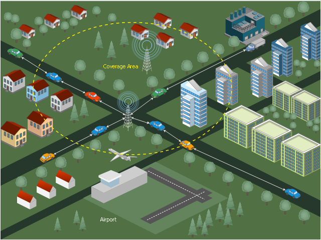
This diagram sample illustrates the cooperative vehicular delay-tolerant network operation.
"Delay-tolerant networking (DTN) is an approach to computer network architecture that seeks to address the technical issues in heterogeneous networks that may lack continuous network connectivity. Examples of such networks are those operating in mobile or extreme terrestrial environments, or planned networks in space.
Recently, the term disruption-tolerant networking has gained currency in the United States due to support from DARPA, which has funded many DTN projects. Disruption may occur because of the limits of wireless radio range, sparsity of mobile nodes, energy resources, attack, and noise." [Delay-tolerant networking. Wikipedia]
"Routing in delay-tolerant networking concerns itself with the ability to transport, or route, data from a source to a destination, which is a fundamental ability all communication networks must have. Delay- and disruption-tolerant networks (DTNs) are characterized by their lack of connectivity, resulting in a lack of instantaneous end-to-end paths. In these challenging environments, popular ad hoc routing protocols such as AODV and DSR fail to establish routes. This is due to these protocols trying to first establish a complete route and then, after the route has been established, forward the actual data. However, when instantaneous end-to-end paths are difficult or impossible to establish, routing protocols must take to a "store and forward" approach, where data is incrementally moved and stored throughout the network in hopes that it will eventually reach its destination. A common technique used to maximize the probability of a message being successfully transferred is to replicate many copies of the message in hopes that one will succeed in reaching its destination." [Routing in delay-tolerant networking. Wikipedia]
The example "Cooperative vehicular delay-tolerant network diagram" was created using the ConceptDraw PRO diagramming and vector drawing software extended with the Vehicular Networking solution from the Computer and Networks area of ConceptDraw Solution Park.
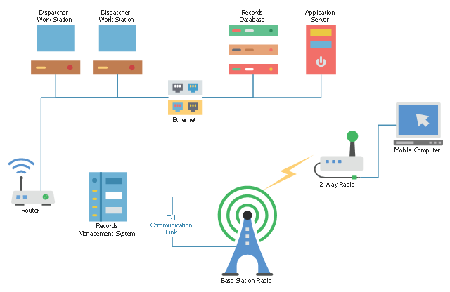
This telecommunication diagram sample shows the Mobile 2-Way Radio Network. It was designed on the base of the Diagram – Mobile 2-Way Radio Network from the "Telecommunications Handbook for Transportation Professionals: The Basics of Telecommunications" on the website of the Office of Operations of the Federal Highway Administration, the U.S. Department of Transportation.
"Mobile 2-Way Radio
Generally used between vehicles for wide area communication in a Private Land Mobile Radio Service (PLMRS) on frequencies set aside by the Federal Communications Commission (FCC) for that purpose. The system is used by DOT maintenance groups to facilitate operations between work crews and a central (or regional) dispatch center. Under the definition of the National Architecture, this is a wide-area mobile communication system. These same systems can also be used to coordinate joint operations between Police Departments and the DOT. These systems can also provide for an exchange of digital data information."
[ops.fhwa.dot.gov/ publications/ telecomm_ handbook/ chapter3.htm]
The telecom diagram example "Mobile 2-way radio network" was created using the ConceptDraw PRO diagramming and vector drawing software extended with the Computers and Communications solution from the Illustration area of ConceptDraw Solution Park.
Cisco Optical. Cisco icons, shapes, stencils and symbols
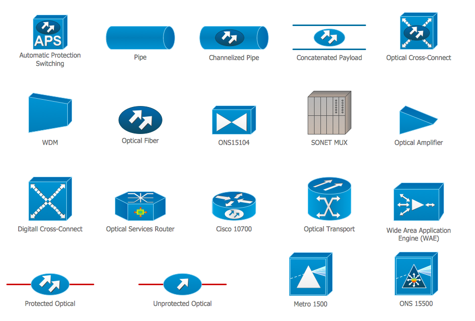
The ConceptDraw vector stencils library Cisco Optical contains symbols for drawing the computer network diagrams.
 Telecommunication Network Diagrams
Telecommunication Network Diagrams solution extends ConceptDraw PRO software with samples, templates, and great collection of vector stencils to help the specialists in a field of networks and telecommunications, as well as other users to create Computer systems networking and Telecommunication network diagrams for various fields, to organize the work of call centers, to design the GPRS networks and GPS navigational systems, mobile, satellite and hybrid communication networks, to construct the mobile TV networks and wireless broadband networks.
Telecommunication networks. Computer and Network Examples
A Telecommunications network is a network of nodes, links, trunks and telephone switches that are connected, operated by telephone companies and realize telephone, audio, visual and data communications among the users. The telecommunications network can also include Internet, microwave, wireless equipment. This example was created in ConceptDraw PRO using the Computer and Networks Area of ConceptDraw Solution Park and shows the Telecommunications network.
Active Directory Network. Computer and Network Examples
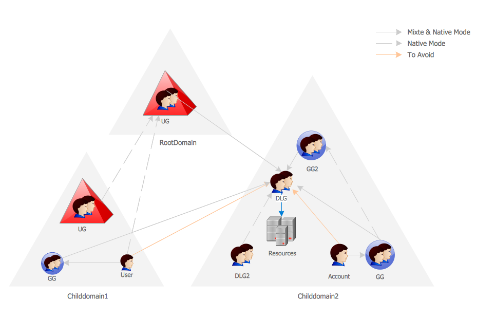
It’s quite a difficult task to manage the computer network today. But ConceptDraw PRO with Computer and Networks solution can help to the system and network administrators plan, create and support the work of their networks.
Star Network Topology
Star is a basic computer network topology in which all nodes (computers and peripheral devices) of the network are connected to the central hub or switch with a point-to-point connection, forming a physical network segment. Such network segment can function separately or as a part of complex network topology. The switch is a server, the peripherals are the clients. The large workload and functions of network management are entrusted on the central computer, all information exchange goes through it, so it must to be obligatory the most powerful. The star network topology is a simple topology for design and implementation. Its advantages are high performance, flexible administration capabilities, simplicity of adding additional nodes and search of faults, the fact that a failure of one workstation doesn't affect the work of entire network. But the failure of central hub will result the failure of whole network or network segment - it's the main disadvantage. Use the ConceptDraw PRO with Computer and Networks solution to designing Star Network Topology Diagrams fast and easy.
Aircraft - Design Elements
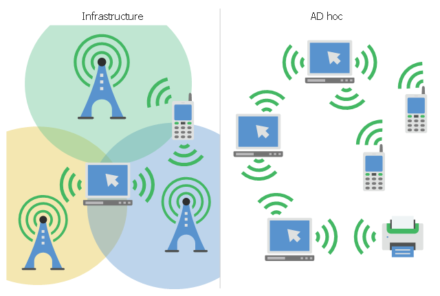
The vector stencils library Aircraft contains clipart of aerospace objects, transportation vehicles, office buildings, and ancillary facilities for ConceptDraw PRO diagramming and vector drawing software.This infographic sample visualizes the Conventional and wireless ad hoc network. It was designed on the base of the Wikimedia Commons file: Běžná bezdrátová síť a ad hoc síť.png.
[commons.wikimedia.org/ wiki/ File:B%C4%9B%C5%BEn%C3%A1_ bezdr%C3%A1tov%C3%A1_ s%C3%AD%C5%A5_ a_ ad_ hoc_ s%C3%AD%C5%A5.png]
This file is licensed under the Creative Commons Attribution-Share Alike 4.0 International license. [creativecommons.org/ licenses/ by-sa/ 4.0/ deed.en]
"A wireless ad hoc network (WANET) is a decentralized type of wireless network. The network is ad hoc because it does not rely on a pre existing infrastructure, such as routers in wired networks or access points in managed (infrastructure) wireless networks. Instead, each node participates in routing by forwarding data for other nodes, so the determination of which nodes forward data is made dynamically on the basis of network connectivity. In addition to the classic routing, ad hoc networks can use flooding for forwarding data.
Wireless mobile ad hoc networks are self-configuring, dynamic networks in which nodes are free to move. Wireless networks lack the complexities of infrastructure setup and administration, enabling devices to create and join networks "on the fly" – anywhere, anytime." [Wireless ad hoc network. Wikipedia]
The infographic example "Conventional and wireless ad hoc network" was created using the ConceptDraw PRO diagramming and vector drawing software extended with the Computers and Communications solution from the Illustration area of ConceptDraw Solution Park.
Local area network (LAN). Computer and Network Examples
Local Area Network (LAN) is a network which consists of computers and peripheral devices connected each other and to the local domain server, and covers a little territory or small number of buildings, such as home, school, laboratory, office, etc. LAN serves for few hundreds of users. It includes many cables and wires, and demands to design previously a Network diagram. All local area network devices can use the shared printers and disk storage. ConceptDraw PRO is a perfect network diagramming software with examples of LAN Diagrams, templates and predesigned vector objects. ConceptDraw PRO is the ideal choice for network engineers and network designers who need to draw fast and easy Local Area Network Diagrams, for IT specialists, developers and other IT professionals which need to visualize the communication schemes of LAN and visually document the LAN's physical structure and arrangement in houses, offices and other buildings. Ready-to-use vector objects from Computer Network Diagrams solution will help you design LAN diagrams in minutes.
- Mobile Tower Visio Drawing
- Phone networks. Computer and Network Examples | Mobile satellite ...
- Mobile 2-way radio network | Telecommunication networks - Vector ...
- Cell Tower 3d Stencil
- How To use Switches in Network Diagram | VMware vNetwork ...
- Radio networks. Computer and Network Examples | Wireless ...
- Cell Tower Visio Stencil
- Radio Waves Png Clipart
- Mobile 2-way radio network | Vertex - Vector stencils library | Design ...
- Visio Stencil Towers
