ERD Symbols and Meanings


Network Glossary Definition


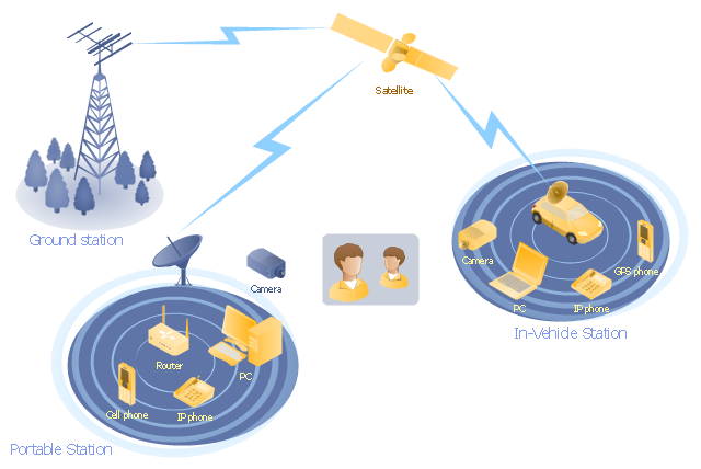
"Mobile satellite systems help connect remote regions, vehicles, ships, people and aircraft to other parts of the world and/ or other mobile or stationary communications units, in addition to serving as navigation systems." [Satellite. Mobile satellite systems. Wikipedia]
"A communications satellite or comsat is an artificial satellite sent to space for the purpose of telecommunications.
... communications satellites ... are ... used for mobile applications such as communications to ships, vehicles, planes and hand-held terminals, and for TV and radio broadcasting." [Communications satellite. Wikipedia]
This mobile satellite communication network diagram was created using the ConceptDraw PRO diagramming and vector drawing software extended with the Telecommunication Network Diagrams solution from the Computer and Networks area of ConceptDraw Solution Park.
Mobile satellite network diagram
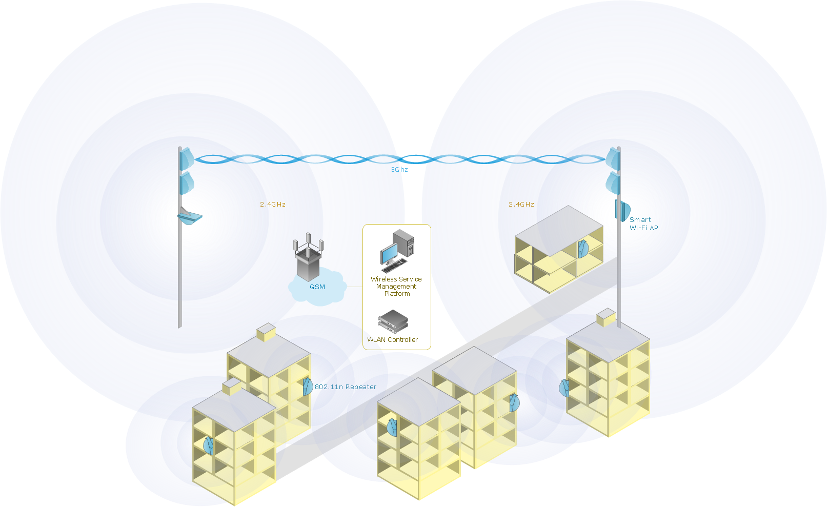
Wireless Network Drawing
Entity Relationship Diagram - ERD - Software for Design Crows Foot ER Diagrams
_Win_Mac.png)
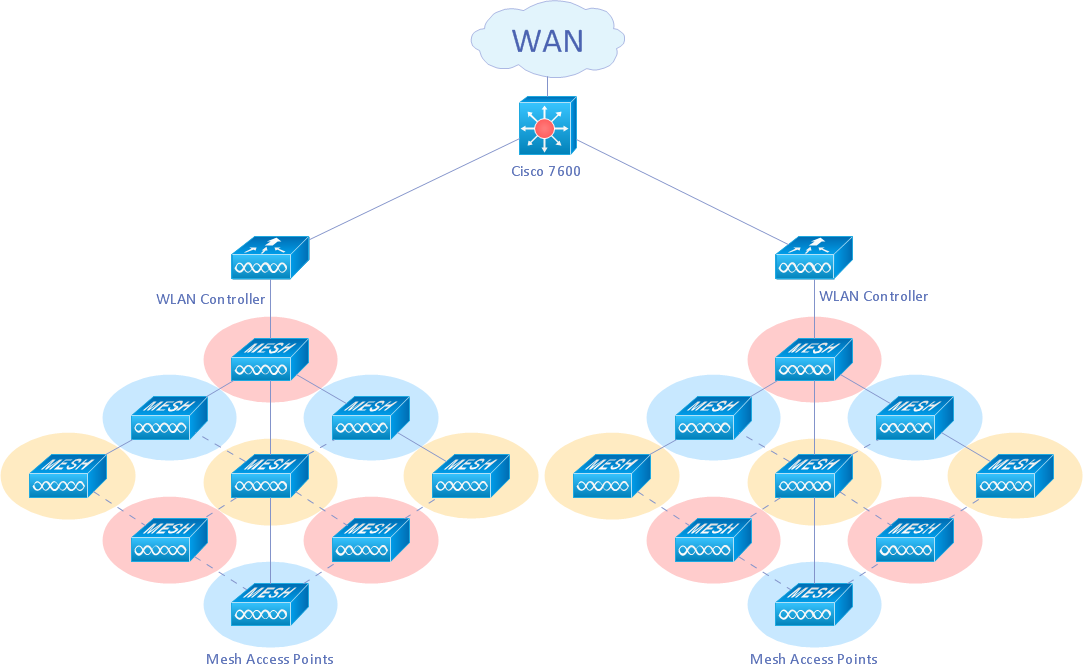
Tree Network Topology Diagram

Calculate the cost of creating or updating a wireless computer network
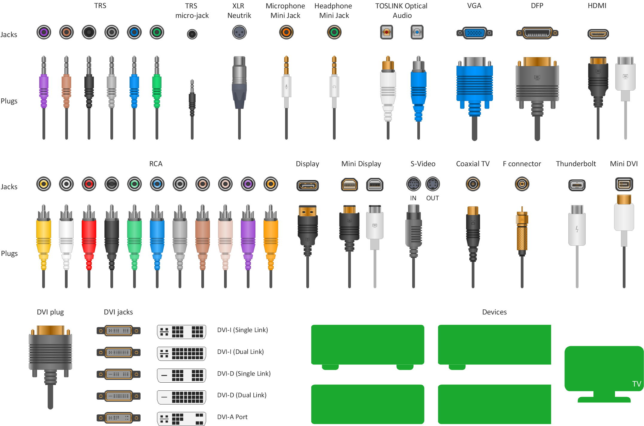
Standard Universal Audio & Video Connection Types
Introduction to Cloud Computing Architecture

 Computer Network Diagrams
Computer Network Diagrams solution extends ConceptDraw DIAGRAM software with samples, templates and libraries of vector icons and objects of computer network devices and network components to help you create professional-looking Computer Network Diagrams, to plan simple home networks and complex computer network configurations for large buildings, to represent their schemes in a comprehensible graphical view, to document computer networks configurations, to depict the interactions between network's components, the used protocols and topologies, to represent physical and logical network structures, to compare visually different topologies and to depict their combinations, to represent in details the network structure with help of schemes, to study and analyze the network configurations, to communicate effectively to engineers, stakeholders and end-users, to track network working and troubleshoot, if necessary.
- Satellite Visio Stencil
- Mobile satellite communication network diagram | Network Diagram ...
- Hybrid satellite and common carrier network diagram | Satellite ...
- Wide area network (WAN) topology. Computer and Network ...
- Mobile satellite communication network diagram ...
- Network Diagram Examples | Telecommunication Network ...
- Wireless access point - Network diagram | Hotel Network Topology ...
- Hybrid satellite and common carrier network diagram | Satellite ...
- Hybrid satellite and common carrier network diagram | Mobile ...
- Computer network - Vector stencils library | Technology - Vector ...