The vector stencils library "Alarm and access control" contains 80 shapes of digital proximity equipment, locking hardware, and access control equipment. Use it for drawing security and access plans of intrusion systems, time and attendance systems, and card and code access control security systems with ConceptDraw PRO software extended with the Security and Access Plans solution from the Building Plans area of ConceptDraw Solution Park.
Card reader with keypad
Biometric access
Card access
Keypad device
Keypad
Security keypad

Horn / siren
Weatherproof horn / siren
Horn / strobe
Strobe

Card reader with time
Turnstile
Revolving door
Traffic arm
Vehicle loop detector
Smoke detector
Heat detector
Gas detector
Carbon monoxide detector
Flood sensor
Electronic lock
Exit device
Pushbutton

Panic button

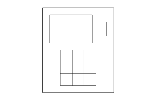
Camera with keypad
Camera

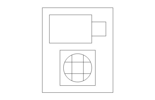
Camera with intercom
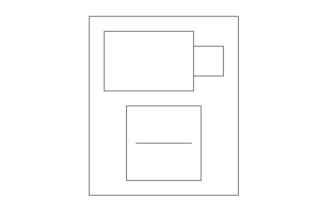
Camera with card reader
Security window screen
Window contact sensor
Vibration / shock sensor
Screen alarm
Glass break detector
Door contact sensor
Floor mat

Driveway sensor
Overhead door contact sensor

Wall motion sensor
Floor motion sensor

Security control unit
Security door contact
Security control panel
Security card reader
Motion detector

Master intercom

Magnetic lock, security door alarm
Intercom unit
Electric door strike
Electric door opener
Door buzzer
Door chime
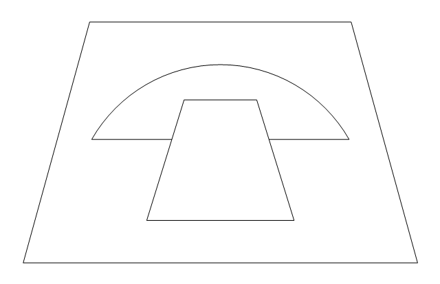
Doorbell
Volumetric capacity detector
Siren
Receiver

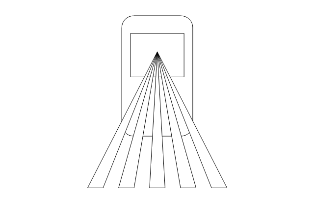
PIR field of view

Mains supply power source

Infrared detector
Heat detector
Foil on glass detector
Dial-up remote equipment
Beam fence disturbance
User control keyswitch
User control digital keypad
Ultrasonic transceiver
Transformer

Space detection device
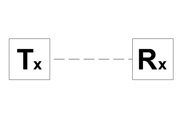
Slave tape dialer
Slave digital communicator
Remote zone annunciator
Passive infrared
Microwave transceiver
Line cut monitor
Infrasonic
Foil

Emergency power / battery

Dual technology device

Control unit

Contact switch surface

Contact switch flush
ERD Symbols and Meanings


Security Plans
Entity Relationship Diagram Symbols

How To Create CCTV Network Diagram

The vector stencils library Alarm and access control contains 80 symbols of digital proximity equipment, locking hardware, and access control equipment.
"An alarm device or system of alarm devices gives an audible, visual or other form of alarm signal about a problem or condition. Alarm devices are often outfitted with a siren." [Alarm device. Wikipedia]
"An access control point, which can be a door, turnstile, parking gate, elevator, or other physical barrier, where granting access can be electronically controlled. Typically, the access point is a door. An electronic access control door can contain several elements. At its most basic, there is a stand-alone electric lock. The lock is unlocked by an operator with a switch. To automate this, operator intervention is replaced by a reader. The reader could be a keypad where a code is entered, it could be a card reader, or it could be a biometric reader. Readers do not usually make an access decision, but send a card number to an access control panel that verifies the number against an access list. To monitor the door position a magnetic door switch can be used. In concept, the door switch is not unlike those on refrigerators or car doors. Generally only entry is controlled, and exit is uncontrolled. In cases where exit is also controlled, a second reader is used on the opposite side of the door. In cases where exit is not controlled, free exit, a device called a request-to-exit (REX) is used. Request-to-exit devices can be a push-button or a motion detector. When the button is pushed, or the motion detector detects motion at the door, the door alarm is temporarily ignored while the door is opened. Exiting a door without having to electrically unlock the door is called mechanical free egress. This is an important safety feature. In cases where the lock must be electrically unlocked on exit, the request-to-exit device also unlocks the door." [Access control. Wikipedia]
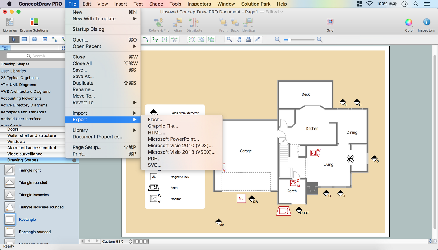
Use the design elements library Alarm and access control for drawing layout floor plans, blueprints, and wiring diagrams of intrusion systems, time and attendance systems, card and code access control security systems, internal and external security control systems using the ConceptDraw PRO diagramming and vector drawing software.
The shapes library Alarm and access control is included in the Security and Access Plans solution from the Building Plans area of ConceptDraw Solution Park.
"An alarm device or system of alarm devices gives an audible, visual or other form of alarm signal about a problem or condition. Alarm devices are often outfitted with a siren." [Alarm device. Wikipedia]
"An access control point, which can be a door, turnstile, parking gate, elevator, or other physical barrier, where granting access can be electronically controlled. Typically, the access point is a door. An electronic access control door can contain several elements. At its most basic, there is a stand-alone electric lock. The lock is unlocked by an operator with a switch. To automate this, operator intervention is replaced by a reader. The reader could be a keypad where a code is entered, it could be a card reader, or it could be a biometric reader. Readers do not usually make an access decision, but send a card number to an access control panel that verifies the number against an access list. To monitor the door position a magnetic door switch can be used. In concept, the door switch is not unlike those on refrigerators or car doors. Generally only entry is controlled, and exit is uncontrolled. In cases where exit is also controlled, a second reader is used on the opposite side of the door. In cases where exit is not controlled, free exit, a device called a request-to-exit (REX) is used. Request-to-exit devices can be a push-button or a motion detector. When the button is pushed, or the motion detector detects motion at the door, the door alarm is temporarily ignored while the door is opened. Exiting a door without having to electrically unlock the door is called mechanical free egress. This is an important safety feature. In cases where the lock must be electrically unlocked on exit, the request-to-exit device also unlocks the door." [Access control. Wikipedia]
Use the design elements library Alarm and access control for drawing layout floor plans, blueprints, and wiring diagrams of intrusion systems, time and attendance systems, card and code access control security systems, internal and external security control systems using the ConceptDraw PRO diagramming and vector drawing software.
The shapes library Alarm and access control is included in the Security and Access Plans solution from the Building Plans area of ConceptDraw Solution Park.
Alarm and access control symbols

 Security and Access Plans
The Security and Access Plans solution may be utilized in order to develop detailed equipment and cabling layout plans, blueprints, and wiring diagrams on internal and external security and access control systems, video surveillance and closed-circuit television (CCTV) systems. IT specialists, security managers, and other guards may use it to quickly design security plans and access plans, security chart, physical security plan, access chart, or access scheme on desire.
 Network Layout Floor Plans
Network Layout Floor Plans solution extends ConceptDraw DIAGRAM software functionality with powerful tools for quick and efficient documentation the network equipment and displaying its location on the professionally designed Network Layout Floor Plans. Never before creation of Network Layout Floor Plans, Network Communication Plans, Network Topologies Plans and Network Topology Maps was not so easy, convenient and fast as with predesigned templates, samples, examples and comprehensive set of vector design elements included to the Network Layout Floor Plans solution. All listed types of plans will be a good support for the future correct cabling and installation of network equipment.
The vector stencils library "Cybersecurity" contains 24 cybersecurity icons.
Use it to design your computer and telecom illustrations and infographics with ConceptDraw PRO diagramming and vector drawing software.
The vector stencils library "Cybersecurity" is included in the Computers and Communications solution from the Illustration area of ConceptDraw Solution Park.
Use it to design your computer and telecom illustrations and infographics with ConceptDraw PRO diagramming and vector drawing software.
The vector stencils library "Cybersecurity" is included in the Computers and Communications solution from the Illustration area of ConceptDraw Solution Park.
Danger file folder

Antivirus

Privacy

Lock

Key

Web protection

Screen padlock

Login

Web key

Lock properties

CCTV camera

Hand touch

Touch screen

Server security

Server lock

Server unlock

Micro SIM card

Alarm file

Repair

Phonendoscope

Aid kit

Savings protection

System setting

Robot

 Entity-Relationship Diagram (ERD)
An Entity-Relationship Diagram (ERD) is a visual presentation of entities and relationships. That type of diagrams is often used in the semi-structured or unstructured data in databases and information systems. At first glance ERD is similar to a flowch
- Card Lock Cad Symbols
- Panic Switch Drawing Symbol
- Symbol Of Proximity Sensor
- Security and Access Plans | How to Draw a Security and Access ...
- Alarm and access control - Vector stencils library | Security and ...
- Design elements - Alarm and access control | Electrical Symbols ...
- Security System Door Contact Symbols
- Electronic Transformer Unit Symbol
- Design elements - Alarm and access control | Security and Access ...
- Security system floor plan | Design elements - Initiation and ...