Mechanical Drawing Symbols

Bubble diagrams in Landscape Design with ConceptDraw DIAGRAM
Create Floor Plans Easily with ConceptDraw DIAGRAM


The vector stencils library "Valve assembly" contains 141 symbols of pressure and flow regulators, flow direction indicators, controls, and symbols to design flow paths of control valves in fluid power systems.
Use these valve assembly shapes to design the engineering drawings of hydraulic and pneumatic valve assemblies
in the ConceptDraw PRO diagramming and vector drawing software extended with the Mechanical Engineering solution from the Engineering area of ConceptDraw Solution Park.
www.conceptdraw.com/ solution-park/ engineering-mechanical
2 position 2,3,4 port (fin. pos.)
-valve-assembly---vector-stencils-library.png--diagram-flowchart-example.png)
2 position 2,3,4 port (infin. pos.)
-valve-assembly---vector-stencils-library.png--diagram-flowchart-example.png)
2 position 2,3,4 port (ext., fin.pos.)
-valve-assembly---vector-stencils-library.png--diagram-flowchart-example.png)
2 position 2,3,4 port (ext., infin. pos.)
-valve-assembly---vector-stencils-library.png--diagram-flowchart-example.png)
2 position 5 port (fin. pos.)
-valve-assembly---vector-stencils-library.png--diagram-flowchart-example.png)
2 position 5 port (infin. pos.)
-valve-assembly---vector-stencils-library.png--diagram-flowchart-example.png)
2 position 5 port (ext., fin.pos.)
-valve-assembly---vector-stencils-library.png--diagram-flowchart-example.png)
2 position 5 port (ext., infin. pos.)
-valve-assembly---vector-stencils-library.png--diagram-flowchart-example.png)
3 position 2,3,4 port (fin. pos.)
-valve-assembly---vector-stencils-library.png--diagram-flowchart-example.png)
3 position 2,3,4 port (infin. pos.)
-valve-assembly---vector-stencils-library.png--diagram-flowchart-example.png)
3 position 2,3,4 port (ext., fin.pos.)
-valve-assembly---vector-stencils-library.png--diagram-flowchart-example.png)
3 position 2,3,4 port (ext., infin. pos.)
-valve-assembly---vector-stencils-library.png--diagram-flowchart-example.png)
3 position 5 port (fin. pos.)
-valve-assembly---vector-stencils-library.png--diagram-flowchart-example.png)
3 position 5 port (infin. pos.)
-valve-assembly---vector-stencils-library.png--diagram-flowchart-example.png)
3 position 5 port (ext., fin.pos.)
-valve-assembly---vector-stencils-library.png--diagram-flowchart-example.png)
3 position 5 port (ext., infin. pos.)
-valve-assembly---vector-stencils-library.png--diagram-flowchart-example.png)
4 position 2,3,4 port (fin. pos.)
-valve-assembly---vector-stencils-library.png--diagram-flowchart-example.png)
4 position 2,3,4 port (infin. pos.)
-valve-assembly---vector-stencils-library.png--diagram-flowchart-example.png)
4 position 2,3,4 port (ext., fin.pos.)
-valve-assembly---vector-stencils-library.png--diagram-flowchart-example.png)
4 position 2,3,4 port (ext., infin. pos.)
-valve-assembly---vector-stencils-library.png--diagram-flowchart-example.png)
4 position 5 port (fin. pos.)
-valve-assembly---vector-stencils-library.png--diagram-flowchart-example.png)
4 position 5 port (infin. pos.)
-valve-assembly---vector-stencils-library.png--diagram-flowchart-example.png)
4 position 5 port (ext., fin.pos.)
-valve-assembly---vector-stencils-library.png--diagram-flowchart-example.png)
4 position 5 port (ext., infin. pos.)
-valve-assembly---vector-stencils-library.png--diagram-flowchart-example.png)
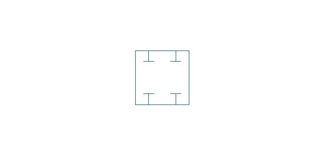
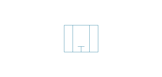
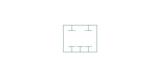
Box 5 port

Box 2,3,4 port

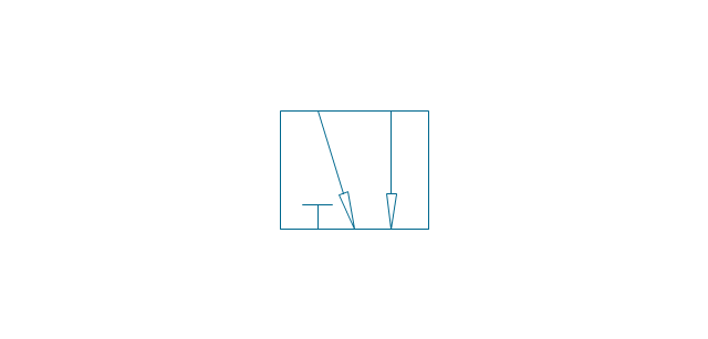
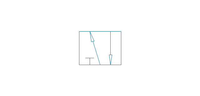
2-port, pneum., 1 arrow
2-port, pneum., 2 arrows

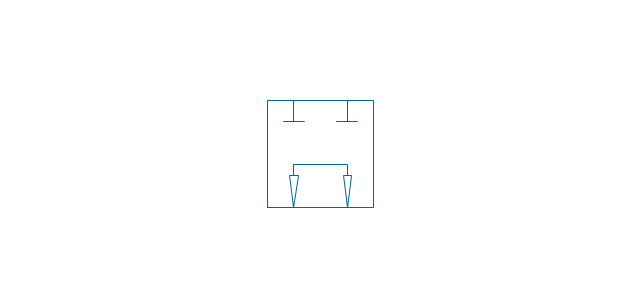
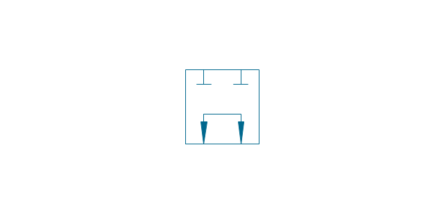
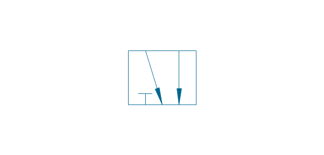
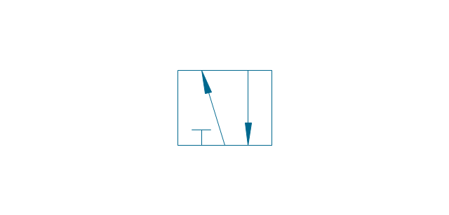
2-port, hydr., 1 arrow
2-port, hydr., 2 arrows

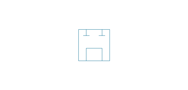
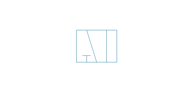
2-port

2-port closed

3-port, pneum., 1 arrow
3-port, pneum., 2 arrows
3-port, hydr., 1 arrow
3-port, hydr., 2 arrows
3-port
3-port crossover, pneum., 1 arrow
3-port crossover, pneum., 2 arrows
3-port crossover, hydr., 1 arrow
3-port crossover, hydr., 2 arrows

3-port crossover

4-port, pneum.
4-port, hydr.
4-port closed
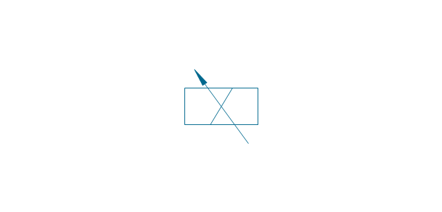
4-port crossed, pneum.

4-port crossed, hydr.

4-port tandem, pneum., 1 arrow
4-port tandem, pneum., 2 arrows
4-port tandem, hydr., 1 arrow
4-port tandem, hydr., 2 arrows
4-port tandem
4-port open
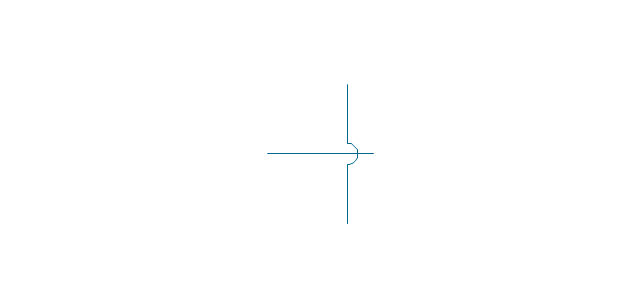
4-port semi-connected
4-port crossover, pneum., 1 arrow
4-port crossover, pneum., 2 arrows
4-port crossover, hydr., 1 arrow
4-port crossover, hydr., 2 arrows
4-port crossover
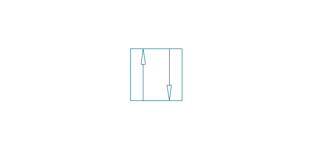
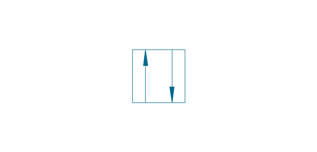
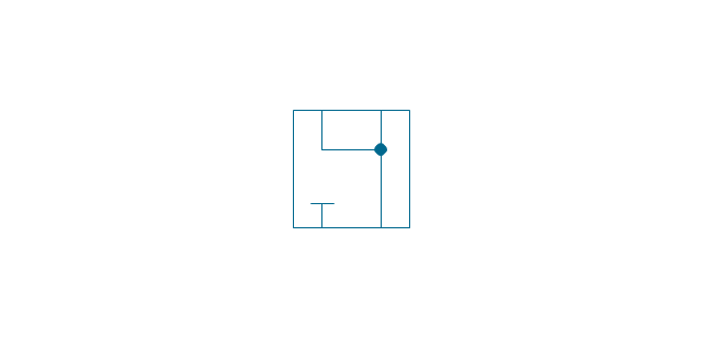
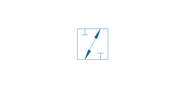
5-port, pneum., arrows same
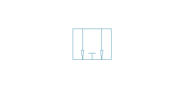
5-port, pneum., arrows opposite
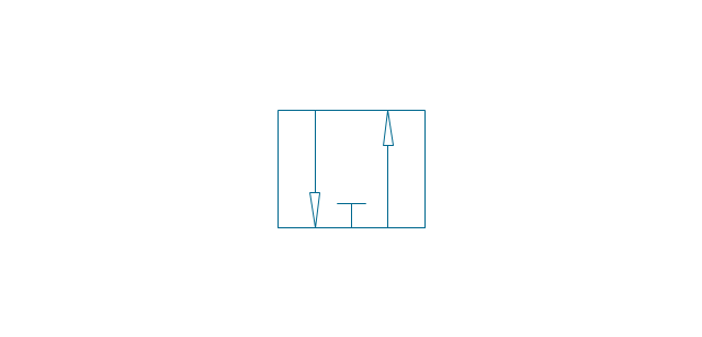
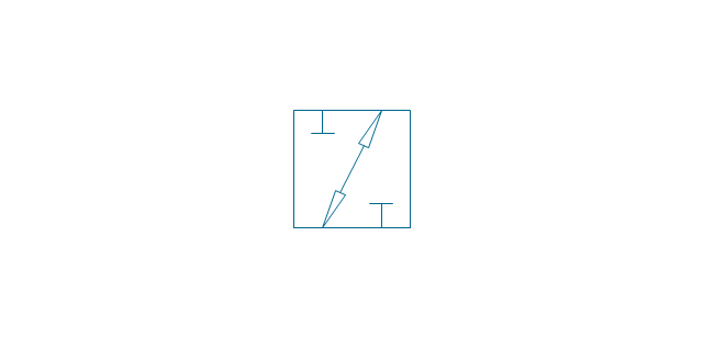
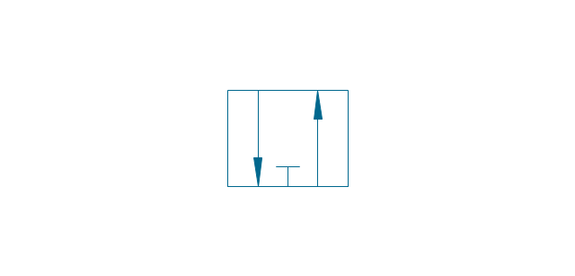
5-port, hydr., arrows same
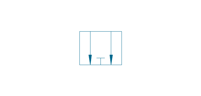
5-port, hydr., arrows opposite
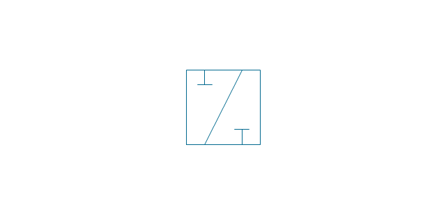
5-port
5-port closed
5-port crossover, pneum., arrows same
5-port crossover, pneum., arrows opposite
5-port crossover, hydr., arrows same
5-port crossover, hydr., arrows opposite
5-port crossover
Spring

Spring, var.
Plunger

Plunger, var.
Roller

Roller (arrow)
-valve-assembly---vector-stencils-library.png--diagram-flowchart-example.png)
One-way trip
One-way trip (arrow)
-valve-assembly---vector-stencils-library.png--diagram-flowchart-example.png)
Manual override

Pull button

Push button

Pull/push button

Lever
Pedal

Treadle

Electric rotor
Electric control, proportional, 1 winding
Electric control, proportional, 2 windings

Electric control, non-proportional, 1 winding

Electric control, non-proportional, 2 windings

Pilot-operated, pneum., 1 arrow, points left

Pilot-operated, pneum., 1 arrow, points right

Pilot-operated, pneum., 2 arrows, points left

Pilot-operated, pneum., 2 arrows, points right

Pilot-operated, pneum.

Pilot-operated, hydr., 1 arrow, points left

Pilot-operated, hydr., 1 arrow, points right

Pilot-operated, hydr., 2 arrows, points left

Pilot-operated, hydr., 2 arrows, points right

Pilot-operated, hydr.

Detent

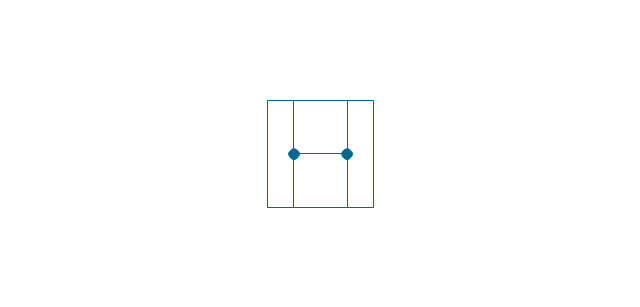
Junction dot

T-junction, con.

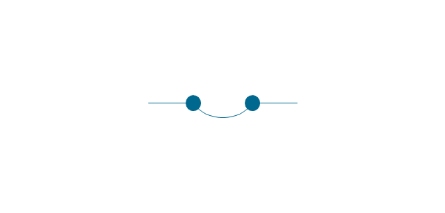
T-junction, discon.

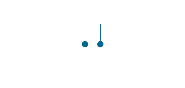
4-way junction, con.
4-way junction, discon.

Crossing
Flexible line
Air bleed, continuous

Air bleed, temporary

Fluid energy

Fluid energy, hydr.

Fluid energy, pneum.

Air exhaust port

Fluid flow, pneum.
Fluid flow, hydr.
Rotary connection (1)
-valve-assembly---vector-stencils-library.png--diagram-flowchart-example.png)
Rotary connection (3)
-valve-assembly---vector-stencils-library.png--diagram-flowchart-example.png)
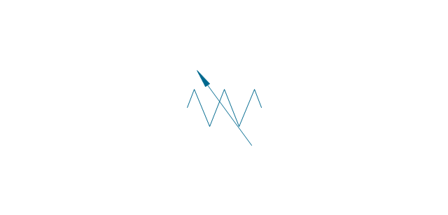
Variable arrow
Curved arrow, top

Curved arrow, bottom

Curved arrow, both ends

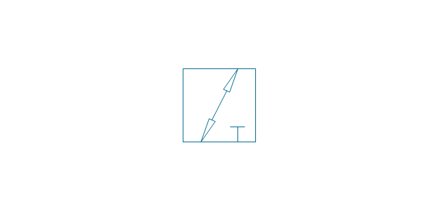
Flow path

Flow path, pneum., 1 arrow
Flow path, hydr., 1 arrow
Flow path, pneum., 2 arrows

Flow path, hydr., 2 arrows

Shaft, top arrow
Shaft, bottom arrow
Shaft, both arrows

Shaft

Rod, right arrow
Rod, left arrow
Rod, both arrows

Over - center

Latch
Closed path

Electric

Restriction

Closed path (double)
-valve-assembly---vector-stencils-library.png--diagram-flowchart-example.png)
Temperature

- ∆ ∆∆ ∆∆∆ Symbol Meaning In Shaft Drawing
- Mechanical Drawing Symbols | Design elements - Bearings ...
- Conventional Symbols In Engineering Drawing On Bearings
- Flowchart For Build Shaft
- Electrical Working Drawings
- Mechanical Drawing Symbols | Basic Diahram Pnumatic Shaft
- Shaft Machining Drawing Symbol
- Mechanical Drawing Symbols | Design elements - Bearings ...
- Process Flowchart | Basic Flowchart Symbols and Meaning | Making ...
- Design elements - Bearings | Drawing Symbol For Thrust Bearing