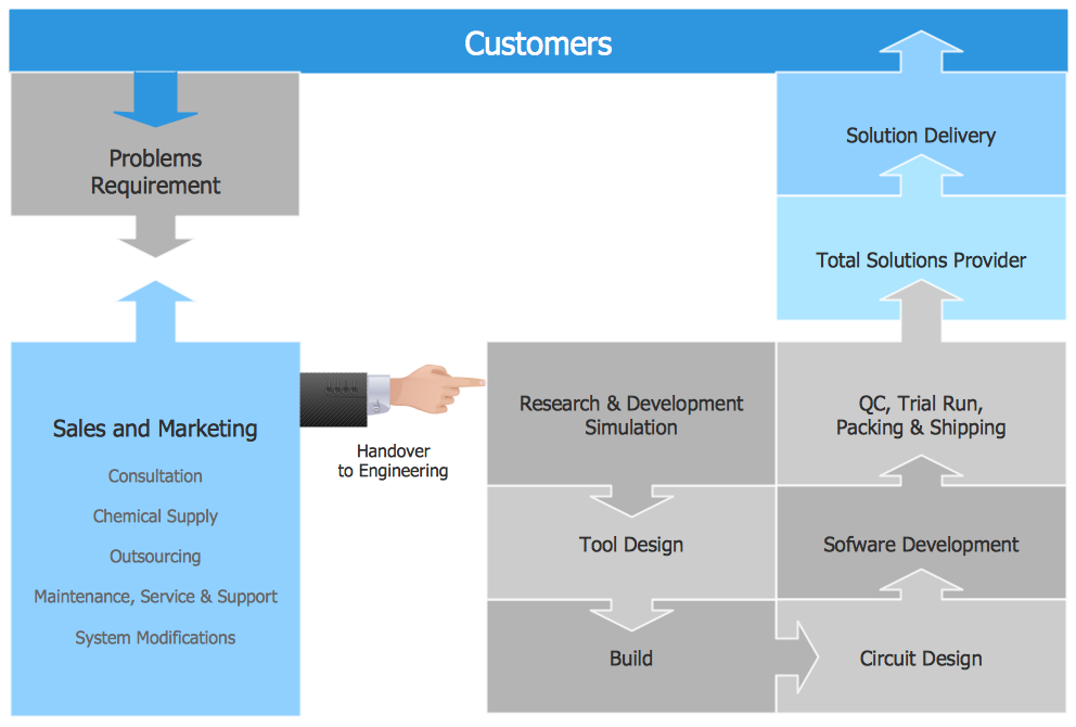
Functional Flow Block Diagram
How To use House Electrical Plan Software


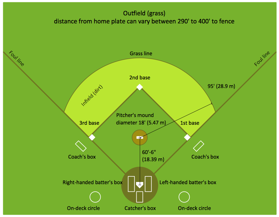
Baseball Diagram – Colored Baseball Field
Functional Block Diagram

Local area network (LAN). Computer and Network Examples
 diagram")

Block Diagram

Data Flow Diagram

Electrical Symbols — Switches and Relays

Types of Flowcharts


 Computer Network Diagrams
Computer Network Diagrams solution extends ConceptDraw DIAGRAM software with samples, templates and libraries of vector icons and objects of computer network devices and network components to help you create professional-looking Computer Network Diagrams, to plan simple home networks and complex computer network configurations for large buildings, to represent their schemes in a comprehensible graphical view, to document computer networks configurations, to depict the interactions between network's components, the used protocols and topologies, to represent physical and logical network structures, to compare visually different topologies and to depict their combinations, to represent in details the network structure with help of schemes, to study and analyze the network configurations, to communicate effectively to engineers, stakeholders and end-users, to track network working and troubleshoot, if necessary.
- How To use Switches in Network Diagram | VMware vNetwork ...
- HVAC Plans | RCP - HVAC layout | How to Create a HVAC Plan | Hvac
- Basic Flowchart Symbols and Meaning | Data Flow Diagrams ...
- IVR network - Vector stencils library | Telecommunication networks ...
- Wireless access point - Network diagram | Hotel Network Topology ...
- Wireless router network diagram | What Is a Wireless Network ...
- Mobile satellite TV network diagram | Network Protocols | Design ...
- Context Diagram Template | DFD Library System | Example of DFD ...
- Network Printer | Network diagrams with ConceptDraw PRO ...
- VoIP call with SIM box and gateway | Android GUI | Sim Wifi Icon Png