Mechanical Drawing Symbols
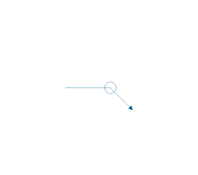
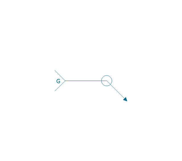
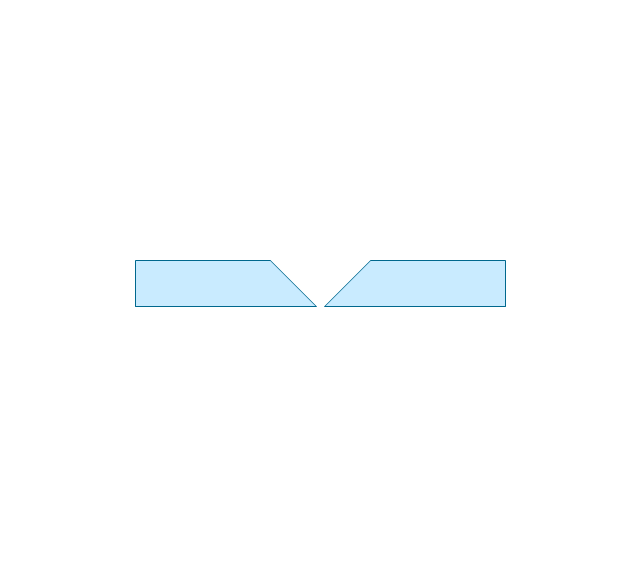
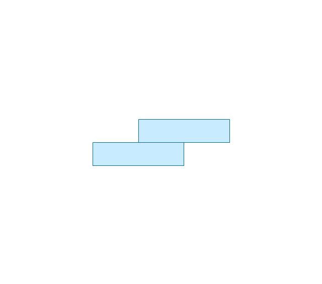
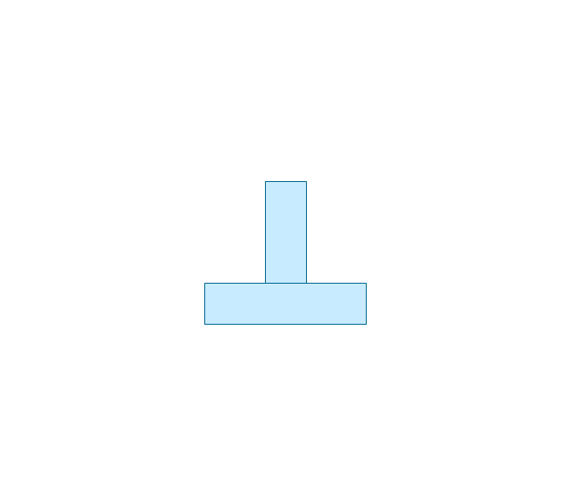
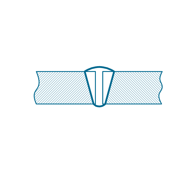
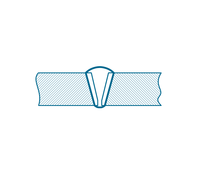
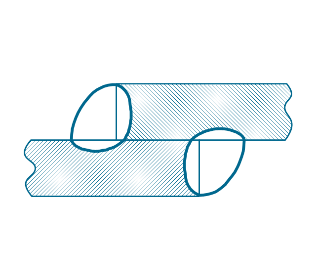
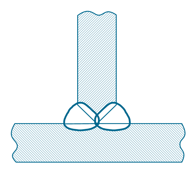
Mechanical Drawings are the special type of technical diagrams that visualize the structure of complex systems and illustrate the information about ventilation, heating, air conditioning, i.e. HVAC systems. These drawings are created on the base of floor plans and reflected ceiling plans, and then become an obligatory part of construction project which is needed directly for construction a building and for receiving a permit on it. Mechanical drawings and diagrams help effectively represent construction, technical and engineering solutions, and also schematics of different mechanical equipment. ConceptDraw DIAGRAM ector drawing software enhanced with Mechanical Engineering solution from Engineering area of ConceptDraw Solution Park provides wide set of effective drawing tools, predesigned mechanical drawing symbols, templates, samples and examples. Use of standardized and recognized mechanical vector symbols helps you design understandable mechanical drawings, diagrams and mechanical engineering schematics.The vector stencils library "Welding" contains 38 welding joint symbols to identify fillets, contours, resistance seams, grooves, surfacing, and backing.
Use it to indicate welding operations on working drawings in the ConceptDraw PRO diagramming and vector drawing software extended with the Mechanical Engineering solution from the Engineering area of ConceptDraw Solution Park.
www.conceptdraw.com/ solution-park/ engineering-mechanical
Use it to indicate welding operations on working drawings in the ConceptDraw PRO diagramming and vector drawing software extended with the Mechanical Engineering solution from the Engineering area of ConceptDraw Solution Park.
www.conceptdraw.com/ solution-park/ engineering-mechanical
 Mechanical Engineering
This solution extends ConceptDraw DIAGRAM.9 mechanical drawing software (or later) with samples of mechanical drawing symbols, templates and libraries of design elements, for help when drafting mechanical engineering drawings, or parts, assembly, pneumatic,
- Mechanical Engineering | Draw The Sketch Of Fillet Weld
- Welding - Vector stencils library | Sketch But Welds Fillet Weld
- Sketch Diagram Of Lap Joint In Welding
- Mechanical Engineering | Skectch A Fillet Joint Diagram
- Sketches Of Various Welding Joints In Engineering
- Fillet Weld Double Bevel
- Example Of Fillet Weld
- Fillet Weld Diagram
- Welded joints types | Mechanical Drawing Symbols | Butt weld ...
- Mechanical Drawing Symbols | Diagram Of Mechanical Fillet
- Weld Diagrams
- Mechanical Engineering | Diagram Sequence Fillet Weld Double ...
- Welding symbols | Elements location of a welding symbol | Design ...
- Butt weld geometry | Welded joints types | Welding - Vector stencils ...
- Sketch A Single Vee But Weld Joint And Indicate The Following
- Welding Shop Sketch Is All Diagram
- Types of Welding in Flowchart | Welding symbols | Welded joints ...
- Engg Drawing Sketch Welder
- Mechanical Drawing Symbols | Mechanical Engineering ...

