"There are two definitions for wireless LAN roaming:
Internal Roaming (1): The Mobile Station (MS) moves from one access point (AP) to another AP within a home network because the signal strength is too weak. An authentication server (RADIUS) performs the re-authentication of MS via 802.1x (e.g. with PEAP). The billing of QoS is in the home network. A Mobile Station roaming from one access point to another often interrupts the flow of data among the Mobile Station and an application connected to the network. The Mobile Station, for instance, periodically monitors the presence of alternative access points (ones that will provide a better connection). At some point, based on proprietary mechanisms, the Mobile Station decides to re-associate with an access point having a stronger wireless signal. The Mobile Station, however, may lose a connection with an access point before associating with another access point. In order to provide reliable connections with applications, the Mobile Station must generally include software that provides session persistence.
External Roaming (2): The MS (client) moves into a WLAN of another Wireless Internet Service Provider (WISP) and takes their services (Hotspot). The user can independently of his home network use another foreign network, if this is open for visitors. There must be special authentication and billing systems for mobile services in a foreign network." [Wireless LAN. Wikipedia]
This Cisco roaming wireless local area network diagram example was created using the ConceptDraw PRO diagramming and vector drawing software extended with the Cisco Network Diagrams solution from the Computer and Networks area of ConceptDraw Solution Park.
WLAN diagram

Used Solutions
"Network planning and design is an iterative process, encompassing topological design, network-synthesis, and network-realization, and is aimed at ensuring that a new telecommunications network or service meets the needs of the subscriber and operator. Network planning process involves three main steps: 1) Topological design: This stage involves determining where to place the components and how to connect them. 2) Network-synthesis: This stage involves determining the size of the components used, subject to performance criteria such as the Grade of Service (GoS). 3) Network realization: This stage involves determining how to meet capacity requirements, and ensure reliability within the network." [Network planning and design. Wikipedia]
This computer network system design diagram example was created using the ConceptDraw PRO diagramming and vector drawing software extended with the Computer and Networks solution from the Computer and Networks area of ConceptDraw Solution Park.
This computer network system design diagram example was created using the ConceptDraw PRO diagramming and vector drawing software extended with the Computer and Networks solution from the Computer and Networks area of ConceptDraw Solution Park.
Network system design
How Do Fishbone Diagrams Solve Manufacturing Problems

Network Diagram Software Logical Network


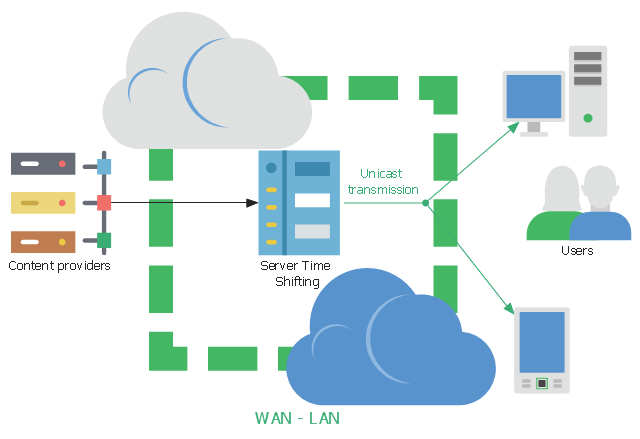
This network diagram sample shows the video on demand (VoD) architecture in a network video recorder (NVR) enviroment. It was designed on the base of Wikimedia Commons file: BaixdemandaArchitecture.png.
[commons.wikimedia.org/ wiki/ File:BaixdemandaArchitecture.png]
This file is licensed under the Creative Commons Attribution-Share Alike 3.0 Unported license. [creativecommons.org/ licenses/ by-sa/ 3.0/ deed.en]
"Video on demand (display) (VOD) are systems which allow users to select and watch/ listen to video or audio content when they choose to, rather than having to watch at a specific broadcast time. IPTV technology is often used to bring video on demand to televisions and personal computers." [Video on demand. Wikipedia]
The network diagram example "VoD architecture in a NVR enviroment" was created using the ConceptDraw PRO diagramming and vector drawing software extended with the Computers and
Communications solution from the Illustration area of ConceptDraw Solution Park.
Network diagram
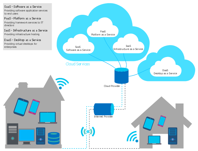
This cloud computing diagram example was drawn on the base of Wikimedia Commons file: Schéma-Cloud-Computing.png. [commons.wikimedia.org/ wiki/ File:Schéma-Cloud-Computing.png]
This file is licensed under the Creative Commons Attribution 3.0 Unported license. [creativecommons.org/ licenses/ by/ 3.0/ deed.en]
"Service models
Though service-oriented architecture advocates "everything as a service" (with the acronyms EaaS or XaaS or simply aas), cloud-computing providers offer their "services" according to different models, which happen to form a stack: infrastructure-, platform- and software-as-a-service." [Cloud computing. Wikipedia]
The example "Cloud computing diagram" was drawn using ConceptDraw PRO software extended with the Cloud Computing Diagrams solution from the Computer and Networks area of ConceptDraw Solution Park.
Cloud service models
This example was designed on the base of the diagram from the article "How secure is that mobile app?" by N.V. Fleming on the website of the U.S. Federal Trade Commission (FTC).
"Neither company validated security certificates to make sure the app was sending the information to the right place. That left users vulnerable to “man in the middle attacks.” An attacker could trick the app into letting him access communications between the app and the online service. Neither the person using the app nor the online service would know the attacker was there." [consumer.ftc.gov/ blog/ how-secure-mobile-app]
The cybersecurity diagram example "Mobile app security" was created using the ConceprDraw PRO software extended with the Network Security Diagrams solution from the Computer and Neworks area of ConceptDraw Solution Park.
Computer security diagram

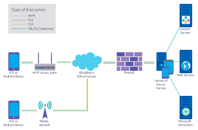
This example was designed on the base of the diagram from the "BYOD Guidance: BlackBerry Secure Work Space" on the website of the UK Communications Electronics Security Group (CESG).
"Secure Work Space (SWS) for iOS and Android is a containerisation, application-wrapping and secure connectivity option that delivers a higher level of control and security to iOS and Android devices, all managed through the BlackBerry Enterprise Service (BES) administration console.
Work space applications are secured and separated from personal applications and data. The work space applications include an integrated email, calendar, and contacts application, an enterprise-level secure browser, and a secure document viewing and editing application.
The work browser allows users to securely browse the organisation’s intranet and the Internet. If the device is lost or the employee leaves the organisation, you can chose to delete only corporate information or all information from the device.
...
Recommended network architecture
The walled garden architecture, shown below, aims to limit the impact of a compromise of an EUD and isolate high risk components from high value components where possible. The enterprise servers installed as part of SWS are high value resources that require suitable protection but are also high risk; they perform complex processing tasks that are more likely to contain exploitable vulnerabilities. These competing priorities make securely placing the servers into an existing network challenging, and organisations that wish to deviate from this architecture below should ensure they understand the risks of doing so."
[cesg.gov.uk/ guidance/ byod-guidance-blackberry-secure-work-space]
The cybersecurity diagram example "Recommended network architecture for BlackBerry SWS" was created using the ConceprDraw PRO software extended with the Network Security Diagrams solution from the Computer and Neworks area of ConceptDraw Solution Park.
Computer security diagram
Cisco WAN. Cisco icons, shapes, stencils and symbols

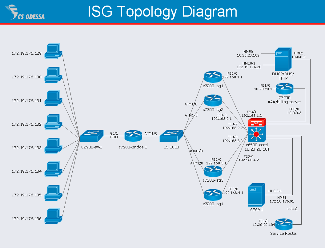
Network Diagram Software ISG Network Diagram
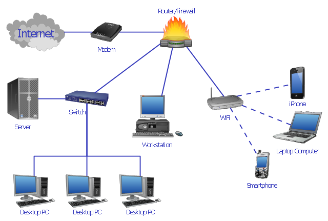
The vector stencils library "Computer network" contains 51 symbols of computer network devices and equipment for drawing computer network diagrams.
"Network Mapping Software.
A number of software tools exist to design computer network diagrams / or generate visual maps of networks, servers, storage, services, data centers, and other peripherals. Broadly, there are two types of software tools - those that help create diagrams manually and those that generate them using automated / semi-automated approaches.
Type of Software.
(1) Manual - allows users to design and draw logical and physical topology diagrams by manually placing icons and connections.
(2) Automated - generate topology diagrams / maps by traversing the network and automatically discovering resident devices or by importing network data." [Comparison of network diagram software. Wikipedia]
ConceptDraw PRO is the software for manual design of computer network diagrams. The solutions of the Computer and Networks area in ConceptDraw Solution Park extend ConceptDraw PRO with vector stencils libraries, templates and examples for creating the computer network diagrams.
The symbols example "Computer network - Vector stencils library" was created using the ConceptDraw PRO diagramming and vector drawing software extended with the Computer and Networks solution from the Computer and Networks area of ConceptDraw Solution Park.
www.conceptdraw.com/ solution-park/ computer-and-networks
Laptop

Desktop computer

Firewall

Bus

Ethernet

Star network

FDDI Ring

Token-ring

Comm-link

Modem

Laser printer

Inkjet printer

Image scanner

City

Ethernet hub

Wireless router

Network switch

iPod Classic

iPhone/ iPod Touch

Xserve RAID

XServe

Apple Thunderbolt Display

Data store

Mac Pro

iMac

RAID

Mainframe

Rack-mountable server

Server

PDA

Cloud

Computer monitor

Workstation

Router

IP Phone

Fax

Mobile phone

Smartphone

Compact Disk

Mouse

Apple Wireless Mouse

Computer keyboard

Apple Keyboard

Radio tower

Satellite dish

Satellite

Webcam

AirPort Extreme

Airport Express

MacBook

iPhone 4

How To create Diagrams for Amazon Web Services architecture
- Fault Tree Diagram For Smartphone Failure
- Server Smartphone Communication Diagram
- Diagram Smartphone
- Local Area Network Diagram
- Android UI Design | MS Visio Look a Like Diagrams | Basic ...
- Diagrams Of A Cell Phone Tower
- Diagram Of A Local Area Network Comprising Of A Modern A ...
- Interaction Overview Diagram | Introductory Guide to Rapid UML ...
- Roaming wireless local area network diagram
- Top 5 Android Flow Chart Apps | Data Flow Diagrams | Technical ...
- Wireless access point - Network diagram | Hotel Network Topology ...
- Phone networks. Computer and Network Examples | Mobile satellite ...
- Smartphone
- Flowchart For Manufacturing A Phone
- Visio Files and ConceptDraw | Active Directory Diagram | Network ...
- Ip Phone Network Diagram
- Roaming wireless local area network diagram | Wireless Network ...
- Smartphone Vector Image Png File
- Call Forwarding with ENUM | Telecommunication Network Diagrams ...
- Smartphone Vector For Diagram